PB170
Well-known member
Does anyone here have any information about the layout of the PowerBook 170/140 motherboard?
Since a couple of months back, I've had problems with my PowerBook 170, somehow related to the AC connector (I've been using the computer more or less daily since I got it back in 2001, averaging about 1000 hours/year, so I'm quite impressed that it lasted this long).
Power to the computer is never interrupted but the voltage varies between 6.5 and 7 V (as opposed to the normal ≈7.6 V). Moving the power cord causes the backlight to flicker, the speaker to pop and sometimes also disturbs the video signal, although this behavior is not constant; sometimes it's fairly insensitive and at other times even the slightest movement is enough. The voltage, however, is constantly at between 6.5 and 7 V. Curiously, when the voltage is lower, the brightness of the backlight gets brighter at all but the highest settings. When running off the battery the computer behaves normally.
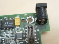
At first I assumed the connector had started to get loose from the board, but upon inspection all solder points looked good and the connector is firmly attached to the board. As a first attempt I tried to simply remelt the solder. This helped slightly at first, but the problems continued.
Following that, I decided to desolder the connector and change it to a known working one from a spare PowerBook, in hopes that this would solve the issue permanently. At first everything seemed to be back to normal, but after a couple of days the problems returned.
Since problems with the connector itself are ruled out, I assume that the traces or vias surrounding it have been damaged in some way. My idea at this point is to solder wires from the pins on the connector to the end of the closest direct trace on the board to make an extra connection (preferably on a free pad somewhere). The problem is, I'm unable to see exactly where the traces go. There appears to be at least one additional layer inside the board, which makes it hard to inspect. From what I can tell there seems to be a positive power layer inside the board and ground traces on the top and bottom, but I'm not sure.
So, my question is: does anyone here have any information about the layout of the board? Also, any ideas are greatly appreciated.
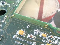
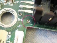
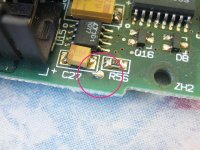
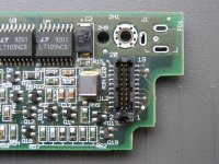
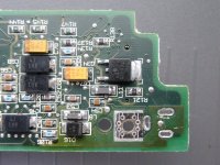
Attached are two pictures of the top and bottom side of the board where the connector is located.


