croissantking
Well-known member
This guide shows the process for a PowerBook 160/165/180, but it should be similar for a 140/145/170. The main difference is that the earlier PowerBooks have a narrower 50(?)-pin connector rather than 72-pin on the later ones.
I carried out this repair on two of my interconnect boards after discovering that the flexible ribbon cable that’s permanently attached to the interconnect board on these early PowerBooks is a common point of failure. If it’s flexed too many times, the fragile solid-core wires break and you start finding problems such as some keys on the keyboard not working. In my case I also found that my brightness controls would not work. See the thread here: https://68kmla.org/bb/index.php?threads/powerbook-145b-repair-attempt-needs-help.45592/
Starting from the beginning I removed the plastic retaining clip from interconnect board side of the ribbon. This is very hard to do without breaking the brittle plastic clips. I used a fine needle on the battery side to gently unhook the clip. From there you can lift up the bracket slightly. Try to do the same on the other side, although I admit that on my first attempt I struggled to unhook the clip near the capacitor, broke it, and needed to use hot glue on reassembly to hold it down.
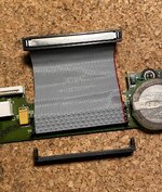
Moving over to the other end of the ribbon, it is a bit easier to detach the clip. Use something pointy to push in the metal nubs as indicated on both sides.
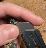
Next, gently lever up either end of the metal retaining bar. The plastic clip will lift off.
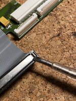
Now you should be here:
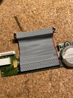
Pay attention to the orientation of the notch on the connector. You’ll need to make sure it’s the same way round when you come to fit the new ribbon. It faces away from the PCB.
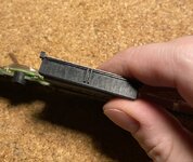
Peel off the ribbon. I started on the connector end.
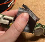
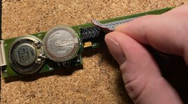
Now, prepare your donor ribbon cable. I had both a 68-pin SCSI cable and and 80-pin ATA cable. The part that I replaced was a 72-pin cable, so it at first seemed sensible to select the ATA cable. But in my case, it was solid core whereas the SCSI cable was stranded. Given that the original’s weakness derives from the single core wires breaking, I thought that a stranded cable would provide a more reliable fix.
In order to make up for the four missing lines on the 68 wire ribbon, what I did was trim it down to 36 wires and then double up. It is very easy to do this, as once you notch the end of the ribbon where you want the split to be, you can cleanly tear it in half - a bit like a cheese string.
Take your newly prepared ribbon and lay it over the top of the old connector. Due to the design of the prongs, the ribbon will auto-locate; so misalignment is not an issue. Just make sure that it’s set over the right pins and that the ribbon is square to
the connector. For this bit, I used a loupe to help me see the detail better.
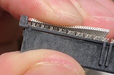
To get things started, I used my thumb to press down from above so that the pins would make an impression in the ribbon. This holds things in place, sort of.
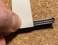
The technique I employed was the use the back of a Stanley knife/box cutter blade to push down on the ribbon next to the crimp pins. As you do this, you start to see the pins break through the cable and some of them will pop through.
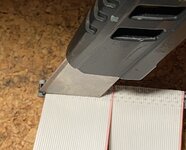
Some of the pins will need a little help popping through. I used the back of my blade to push down next to individual pins. It feels a bit like popping zits.
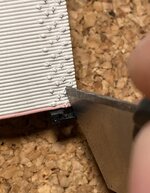
You’ll now hopefully have something that looks like this:
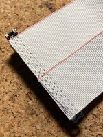
Here I have used the old ribbon cable as a guide to measure where to cut on the new one. I just cut across it with my knife.
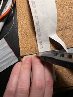
Next, I laid my partially assembled ribbon cable over the crimp pins on the PCB side. You can see that I drew a black line over it which was to help me get the cable in as square as possible. Once I was happy with the alignment I pushed down on the ribbon with my thumb like last time.
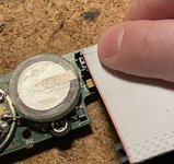
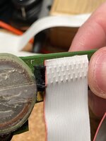
As before, I went over with the back of my blade so that the pins would push through the wires.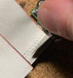
Once I’d done half of it, I used some kapton tape to hold the two parts of the cable together, making it easier to line up the second half.
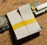
Getting there…
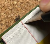
And done.
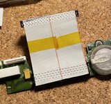
I used a multimeter to check continuity between pins on both ends, and also to check that none of the lines were accidentally bridged to a neighbour. Be aware that some lines are common to each other, particularly those connected to the ground plane. I made a diagram to show which these are which I’ll upload later.
All my connections were good on the first attempt, on both cables. I was really pleased about this.
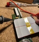
Now the clips go back on:
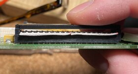
And excess cable can be trimmed off using a sharp blade.
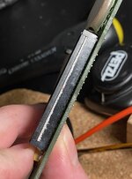
Here’s the finished article. Notice the way that iron filings always build up on the speaker membrane on these interconnect boards.
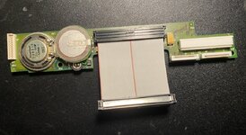
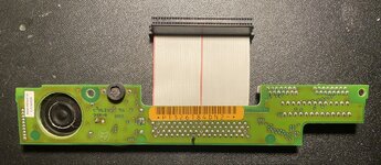
Here is it going into my PowerBook 180 for testing.
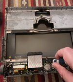
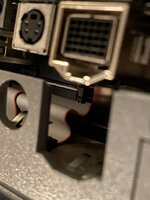
Be aware of how the cable folds when you put the bottom half and top half of the machine together. You are kind of training it at this point and need to make sure it isn’t in a form that will put stress on it. I found the following to be adequate:
I carried out this repair on two of my interconnect boards after discovering that the flexible ribbon cable that’s permanently attached to the interconnect board on these early PowerBooks is a common point of failure. If it’s flexed too many times, the fragile solid-core wires break and you start finding problems such as some keys on the keyboard not working. In my case I also found that my brightness controls would not work. See the thread here: https://68kmla.org/bb/index.php?threads/powerbook-145b-repair-attempt-needs-help.45592/
Starting from the beginning I removed the plastic retaining clip from interconnect board side of the ribbon. This is very hard to do without breaking the brittle plastic clips. I used a fine needle on the battery side to gently unhook the clip. From there you can lift up the bracket slightly. Try to do the same on the other side, although I admit that on my first attempt I struggled to unhook the clip near the capacitor, broke it, and needed to use hot glue on reassembly to hold it down.

Moving over to the other end of the ribbon, it is a bit easier to detach the clip. Use something pointy to push in the metal nubs as indicated on both sides.

Next, gently lever up either end of the metal retaining bar. The plastic clip will lift off.

Now you should be here:

Pay attention to the orientation of the notch on the connector. You’ll need to make sure it’s the same way round when you come to fit the new ribbon. It faces away from the PCB.

Peel off the ribbon. I started on the connector end.


Now, prepare your donor ribbon cable. I had both a 68-pin SCSI cable and and 80-pin ATA cable. The part that I replaced was a 72-pin cable, so it at first seemed sensible to select the ATA cable. But in my case, it was solid core whereas the SCSI cable was stranded. Given that the original’s weakness derives from the single core wires breaking, I thought that a stranded cable would provide a more reliable fix.
In order to make up for the four missing lines on the 68 wire ribbon, what I did was trim it down to 36 wires and then double up. It is very easy to do this, as once you notch the end of the ribbon where you want the split to be, you can cleanly tear it in half - a bit like a cheese string.
Take your newly prepared ribbon and lay it over the top of the old connector. Due to the design of the prongs, the ribbon will auto-locate; so misalignment is not an issue. Just make sure that it’s set over the right pins and that the ribbon is square to
the connector. For this bit, I used a loupe to help me see the detail better.

To get things started, I used my thumb to press down from above so that the pins would make an impression in the ribbon. This holds things in place, sort of.

The technique I employed was the use the back of a Stanley knife/box cutter blade to push down on the ribbon next to the crimp pins. As you do this, you start to see the pins break through the cable and some of them will pop through.

Some of the pins will need a little help popping through. I used the back of my blade to push down next to individual pins. It feels a bit like popping zits.

You’ll now hopefully have something that looks like this:

Here I have used the old ribbon cable as a guide to measure where to cut on the new one. I just cut across it with my knife.

Next, I laid my partially assembled ribbon cable over the crimp pins on the PCB side. You can see that I drew a black line over it which was to help me get the cable in as square as possible. Once I was happy with the alignment I pushed down on the ribbon with my thumb like last time.


As before, I went over with the back of my blade so that the pins would push through the wires.

Once I’d done half of it, I used some kapton tape to hold the two parts of the cable together, making it easier to line up the second half.

Getting there…

And done.

I used a multimeter to check continuity between pins on both ends, and also to check that none of the lines were accidentally bridged to a neighbour. Be aware that some lines are common to each other, particularly those connected to the ground plane. I made a diagram to show which these are which I’ll upload later.
All my connections were good on the first attempt, on both cables. I was really pleased about this.

Now the clips go back on:

And excess cable can be trimmed off using a sharp blade.

Here’s the finished article. Notice the way that iron filings always build up on the speaker membrane on these interconnect boards.


Here is it going into my PowerBook 180 for testing.

Be aware of how the cable folds when you put the bottom half and top half of the machine together. You are kind of training it at this point and need to make sure it isn’t in a form that will put stress on it. I found the following to be adequate:


