I have a PowerBook 5300 that I got for parts and ended up fixing it up and now it runs fine except for the LCD. I replaced the LCD with a black and white screen from a PowerBook 190 and everything worked but the original color screen was just a yellow bar in the middle of the LCD.
I started doing rudimentary tests. If I moved the ribbon cable around the screen would sort of look fine but with the bottom half looked really bad and the paper right of the screen sort of displayed a very fine ghost image of the left of the screen. I figured the ribbon cable was bad so I quickly toned out the cable.
This was a good idea because the more I handled the cable the worse it got. I got all but five lines before the cable was all but useless. Obviously looking for another cable was not going to work since they are all sold out everywhere. Also the ones you can find have the same problem.
I lifted the connectors and built a set of cables by hand. I looked at a sharp LCD version of the cable to figure out the missing five wires I was not sure about. I also verified the five wires by painstakingly tracing them by hand. My goal is to make a ribbon cable myself. Not that I need this machine because it is a parts machine but I was vested and thought it would be fun.
So I set out to making my own cables with wires to make sure the wire placement was correct. I installed my home made cable and got:

Success on my first try. Well sort of. I know you cannot see it very well in this picture but the screen is very vibrant. Maybe this one:

Is better?
Anyway, the contrast and brightness work great (they did not work before). I let it go to sleep and the sleep LED lit up and blinked. The only problem is the upper right of the screen is a black box. I have never seen this before. Has anyone else? Is this a bad LCD panel? Is my wiring off somewhere? I double and triple checked all the wires on the original ribbon cable. I checked all the wires on the new hand built cables.
Is there a way to recover the quarter of the panel? I guess I could try and find another panel but if I can fix this it would make me feel better that the wiring is correct. Anyone have any ideas?
I started doing rudimentary tests. If I moved the ribbon cable around the screen would sort of look fine but with the bottom half looked really bad and the paper right of the screen sort of displayed a very fine ghost image of the left of the screen. I figured the ribbon cable was bad so I quickly toned out the cable.
This was a good idea because the more I handled the cable the worse it got. I got all but five lines before the cable was all but useless. Obviously looking for another cable was not going to work since they are all sold out everywhere. Also the ones you can find have the same problem.
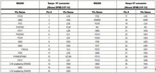
I lifted the connectors and built a set of cables by hand. I looked at a sharp LCD version of the cable to figure out the missing five wires I was not sure about. I also verified the five wires by painstakingly tracing them by hand. My goal is to make a ribbon cable myself. Not that I need this machine because it is a parts machine but I was vested and thought it would be fun.
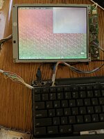
So I set out to making my own cables with wires to make sure the wire placement was correct. I installed my home made cable and got:

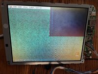
Success on my first try. Well sort of. I know you cannot see it very well in this picture but the screen is very vibrant. Maybe this one:

Is better?
Anyway, the contrast and brightness work great (they did not work before). I let it go to sleep and the sleep LED lit up and blinked. The only problem is the upper right of the screen is a black box. I have never seen this before. Has anyone else? Is this a bad LCD panel? Is my wiring off somewhere? I double and triple checked all the wires on the original ribbon cable. I checked all the wires on the new hand built cables.
Is there a way to recover the quarter of the panel? I guess I could try and find another panel but if I can fix this it would make me feel better that the wiring is correct. Anyone have any ideas?


