• Updated 2023-07-12: Hello, Guest! Welcome back, and be sure to check out this follow-up post about our outage a week or so ago.

How to mod an ATX PSU for 10 Pin Macintosh (for example IIsi, IIci, Quadra 700 and others)

superjer2000

Well-known member
Hi @Von,

I ended up just using a PNP transistor PN2222 rather than the 74LS04 not gate chips I bought. Have a read through the post of mine you quoted looking at the breadboard part as that outlines how everything was connected. Once that was working, I just transferred it to the PCB. 

Let me me know if that doesn't clear it up.  


Von

Well-known member
Hi @superjer2000, I looked at pin diagrams after posting this. I had assumed PN2222 only had 2 pins and it was the 74LS04.  I think I get how this goes together with the 3 pins on the PN2222 and I will update that diagram after some sleep.  

You mentioned that this powers the IIci from the keyboard. Does it also shut the system down when you do Shut Down from the OS?  

THx!

 
Last edited by a moderator:

superjer2000

Well-known member
Hi @superjer2000, I looked at pin diagrams after posting this. I had assumed PN2222 only had 2 pins and it was the 74LS04.  I think I get how this goes together with the 3 pins on the PN2222 and I will update that diagram after some sleep.  

You mentioned that this powers the IIci from the keyboard. Does it also shut the system down when you do Shut Down from the OS?  

THx!
@Von  Yup... IIci soft power works perfectly. Power on and off. Above the breadboard picture is a summary of what Color wires are what.  


Von

Well-known member
Yay, the site is back.

@superjer2000 I went shopping and have 2 of the PN2222's and when it came time for the 1K resistors, the guy behind the counter asked what wattage...

What wattage did you use for this?  The guy thought they looked like 1/2 watt so I left with 4 of those.  The shop didn't have protoboard so I have some on order that should arrive before the weekend.

THx!


trag

Well-known member
For both resistors, worst case, you're connecting 5V to 0V, although the Base should be considerably more limited than that.

Power through a resistor is V^2/R, where V is the voltage drop across the resistor and R is the value of the resistor.     So the maximum powers in the resistors are 5^2/1000 and 5^2/10000   =>   25/1000 and 25/10000   =>  .025 watts and .0025 watts.    So anything from 1/8 watt on up should be fine.   It won't hurt anything to use a 1/2 watt resistor, although it might be slightly more expensive.


superjer2000

Well-known member
For both resistors, worst case, you're connecting 5V to 0V, although the Base should be considerably more limited than that.

Power through a resistor is V^2/R, where V is the voltage drop across the resistor and R is the value of the resistor.     So the maximum powers in the resistors are 5^2/1000 and 5^2/10000   =>   25/1000 and 25/10000   =>  .025 watts and .0025 watts.    So anything from 1/8 watt on up should be fine.   It won't hurt anything to use a 1/2 watt resistor, although it might be slightly more expensive.
Exactly - I just used 1/4 watt resistors as I had those lying around.


Von

Well-known member
For both resistors, worst case, you're connecting 5V to 0V, although the Base should be considerably more limited than that.

Power through a resistor is V^2/R, where V is the voltage drop across the resistor and R is the value of the resistor.     So the maximum powers in the resistors are 5^2/1000 and 5^2/10000   =>   25/1000 and 25/10000   =>  .025 watts and .0025 watts.    So anything from 1/8 watt on up should be fine.   It won't hurt anything to use a 1/2 watt resistor, although it might be slightly more expensive.


Exactly - I just used 1/4 watt resistors as I had those lying around.


Thanks for this guys. Vetco is between work and home so I will swing by and replace the 1/2 with 1/4.  I think all of their 1K resistors were $0.29/each. Hopefully the protoboard will be waiting for me when I get home.


Von

Well-known member
Some good progress made today and I am now paused with a question.

Here is my PN2222 (generic version)
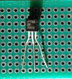
2018-11-11 13.59.21.jpg

I don't have a breadboard so here is how the PN2222 is connected to my SeaSonic PS:

  • Leftmost leg...Purple +5v is connected to the PS and the motherboard (2 complete wires from 2 different SeaSonics), in the middle I have a jumper connecting the PS to the MB and one end of a 1K resistor. The other end of the 1K resistor then feeds through the Green PS_ON connected to the PS; that end is then alligator clipped to the leftmost leg.
  • Center leg has the red alligator clip. In the clip is a 1 K resistor and at the opposite end of the resistor is a grey wire that goes to the MB connector #9.
  • Rightmost leg is connected to the black alligator clip that clips to a black ground coming from the PS.
The above describes the hairball below:
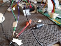
2018-11-11 12.03.03.jpg

I had this setup first attached to my IIci and this did not work. Note that the IIci is fairly new to me and when it arrived its stock PS never fired it up. I added the SeaSonic and that worked fine but it needed to be manually switched. The board has never emitted sound so a recap is in order. I don't know if the caps situation could affect the power on so I decided to move to my IIsi that also needs soft power for its SeaSonic PS.

The IIsi also failed to start in this configuration but it did make a sound and the monitor did briefly light up so some progress.  I then tried removing the 1K resistor between the center leg and the the grey wire connected to the MB at position 9. You can see the grey wire in the red alligator clip with the 1K resistor connected to nothing (apology for the blur on that side of the photo):
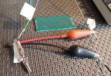
2018-11-11_13_54_14.jpg

This setup worked as expected where both the power button on the keyboard and the power button on the PS fired the IIsi up. The OS also shut the machine down as expected so that is great progress.  I then wondered what purpose the other 1k resistor was offering on the leftmost leg so I tried this:

  • Removed the other 1K resistor
  • Kept the purple +5v connected to the PS and MB but not attached at all to the PN2222
  • Attached the green PS_ON from the PS to the leftmost leg of the PN2222
  • Attached the grey wire in MB position 9 to the center leg of pf the PN2222 (photo above)
  • Rightmost list of PN2222 is still connected to PS ground
Here is what that looked like:
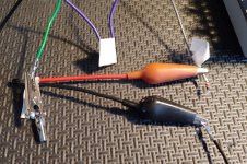
2018-11-11_14_52_37.jpg

This setup with no resistors worked as expected turning the IIsi on from the PS & KB and shutting down completely from the OS.

Can anyone tell me where I strayed from @superjer2000's directions  or why the no capacitors path I found works? 

THx!


Von

Well-known member
FWIW, I swapped back to the IIci and the without capacitor setup and it did not work there.


superjer2000

Well-known member
Hi Von you definitely need the resistors or else you'll burn up the transistor or create a short.  

I wonder if your connections aren't that solid given the use of clips etc...

To confirm. Left leg of transistor is connected to the 1k resistor and the green power on wire on the PSU. The other side of the transistor is connected to the purple PSU 5vsb line and pin 10 of motherboard connector. 

The centre pin pin goes through the 10k resistor and then to pin 9 of the motherboard connector. 

The right leg goes to psu ground.  

You our should be able to test it by seeing the input voltage going to the middle pin. It should be zero and the output line  output voltage on the wire coming from pin going to PSU green should be 5v. If you touch 5v from the standby line to the resistor connected to the middle pin the output line should go low and the supply should turn on. 


Von

Well-known member
I wonder if your connections aren't that solid given the use of clips etc...
I am thinking this may be the case as I had the connections as you described.  I will try to solder it up tomorrow and see how that goes.  THx


Bolle

Well-known member
I don't know if the caps situation could affect the power on 


It does. There are caps in the power on section of the logicboard. If they are bad the IIci will not generate the power on signal.


superjer2000

Well-known member
@Von  I just reread your prior post and it seems like maybe you use 1k resistors only. There should be two different resistor values, a 10k and a 1k. If you just used two x 1k and then tried with no resistors I would try to get the right values and use your other transistor in case the first one was damaged. 

 
Last edited by a moderator:

Von

Well-known member
It does. There are caps in the power on section of the logicboard. If they are bad the IIci will not generate the power on signal.
Thanks for this. The board is going to have an appointment with the caps doctor.

@Von  I just reread your prior post and it seems like maybe you use 1k resistors only. There should be two different resistor values, a 10k and a 1k. If you just used two x 1k and then tried with no resistors I would try to get the right values and use your other transistor in case the first one was damaged. 
Great catch on my bad. I have only 1K caps as I was going from the diagram with the black background, not yours. I will grab some 10K 1/4 watt resistors from Vetco if they are open today.


superjer2000

Well-known member
You should also be able to test this pretty easily without the Seasonic being hooked up to the Macintosh.  Don't hook up Pins 9 and 10 to the Mac motherboard and instead jump +5vsb from the Seasonic to the resistor attached to the middle pin of the transistor.  The seasonic should turn on.  As noted, you should be able to measure this with a multimeter on the output line (green wire).  It should be +5v until you touch the +5vsb to the input line at which point it should go close to 0v.  This will at least tell you if the parts are all working correctly or if a wire is maybe running to the wrong place.

Also for my IIci, I needed to replace a whole bunch of components to get the softpower going and then jumper some traces.  It wasn't anything to do with the seasonic as it wouldn't work with the stock Astec either until I made these repairs.  Unfortunately, capacitor goo ate a number of components and traces.  Hopefully your IIci isn't in as bad of shape as mine was!

 
Last edited by a moderator:

Von

Well-known member
Here is my progress on this.  On Sunday I was able to solder the components I have to the protoboard that arrived.

Purple wire is +5v_SB that goes from the PS to the MB pin 10.  I stripped some insulation from the middle and attached the 1K resistor. The other end of the 1K attaches to the left leg of transistor which is also connected to the Green PS_ON from the MB.

The center leg of the transistor is connected to a 10K resistor and the opposite end of the 10K is connected to the Green wire that connects to the MB at pin 9.

The right leg of the transistor that is connected to the Black wire that goes to the PS:

Front2.jpg

Back2.jpg

I think I have followed the instructions...does this look right? The reason I ask is because it didn't work with KB or PS power button...I used my IIsi as it is freshly recapped and known to have soft power working.

You should also be able to test this pretty easily without the Seasonic being hooked up to the Macintosh.  Don't hook up Pins 9 and 10 to the Mac motherboard and instead jump +5vsb from the Seasonic to the resistor attached to the middle pin of the transistor.  The seasonic should turn on.  As noted, you should be able to measure this with a multimeter on the output line (green wire).  It should be +5v until you touch the +5vsb to the input line at which point it should go close to 0v.  This will at least tell you if the parts are all working correctly or if a wire is maybe running to the wrong place.


I then kept the PS plugged in to power but unplugged from the IIsi MB. At the MB end of the Purple +5v_SB it read 5.07 on the multimeter. At the left leg it read 4.87 v and 0 v on the center leg.

When I take the MB end of the Purple wire and jump it to the opposite end of the 10K resistor, nothing happens. PS does not turn on (I have a drive connected with an LED) and left leg remains at ~ 4.87v.

If I take the +5v_SB and jump directly to the center leg, drive turns on and left leg goes to 0v.  I think the 10K may be the culprit here. For fun I put my other 10K resistor at the end of the +5v_SB and jumped its other end directly to the center leg...nothing happened.

I'd welcome any input on this.

THx!

 
Last edited by a moderator:

Von

Well-known member
The circuit I used is from https://electronicsclub.info/transistorcircuits.htm (Search for inverter).  I used a PN2222 transistor that I had from an old Sparkfun kit I had laying around.  I used the resistor values from the electronicsclub in the circuit.


I first laid everything out on a breadboard to make sure it worked fine with the ATX supply.  The red wire was connected to the power supply +5V standby.  The black wire connected to ground.  The yellow wire connected to the ATX power supply green wire (PS_ON).   The blue wire is the trigger wire that turns on the ATX supply when connected to +5V.  When the blue wire was connected to the +5V standby the power supply turned on as expected.

View attachment 24512

I then...


So I called the shop I got the parts from and it appears that the pins my generic PN2222 are reverse of yours:

[SIZE=11pt]736 2n 3903[/SIZE]

[SIZE=11pt] [/SIZE]

[SIZE=11pt]Looking at the flat side[/SIZE]

[SIZE=11pt] [/SIZE]

[SIZE=11pt]E left[/SIZE]

[SIZE=11pt]B middle[/SIZE]

[SIZE=11pt]C right[/SIZE]

I will give this a try again tomorrow with the transistor aligned opposite of what I had.  Wish me luck.


superjer2000

Well-known member
So I called the shop I got the parts from and it appears that the pins my generic PN2222 are reverse of yours:

[SIZE=11pt]7[/SIZE]36 2n 3903

[SIZE=11pt] [/SIZE]

[SIZE=11pt]Looking at the flat side[/SIZE]

[SIZE=11pt] [/SIZE]

[SIZE=11pt]E left[/SIZE]

[SIZE=11pt]B middle[/SIZE]

[SIZE=11pt]C right[/SIZE]

I will give this a try again tomorrow with the transistor aligned opposite of what I had.  Wish me luck.
Hi Von,

Based on the data sheets, the pinout for the transistors is the same and I think it's pretty standard. 

Are you sure the resistor values are right (verified with multimeter?). The colours look different than mine. 

If if you can wait for a while I can build you a replica of the one I built but you probably wouldn't get it until early January. 


Von

Well-known member
Appreciate the offer @superjer2000 but I planned for 2 of these so I will give it another go with my remaining parts. I too assumed that the pins were standard and I built mine exactly like you did.  I Googled the part number and there are images that show some with the pins reversed.  I also tested the resistors and then measured 1 and 10K so I think I have the right parts.  More to come on this.


superjer2000

Well-known member
Appreciate the offer @superjer2000 but I planned for 2 of these so I will give it another go with my remaining parts. I too assumed that the pins were standard and I built mine exactly like you did.  I Googled the part number and there are images that show some with the pins reversed.  I also tested the resistors and then measured 1 and 10K so I think I have the right parts.  More to come on this.
Now I'm starting to question what I did - When I look at a generic data sheet for the PN2222A it shows the Emitter as being pin 1 (first pin on the left on the flat side).  The Emitter in the circuit diagram is hooked up to ground, but I have my ground connected to pin 3 (i.e. the Collector).  As you note, there do appear to be variations of this transistor (P2N2222A) which has the pins reversed.  Without pulling the heat shrink tubing off the transistor I used, I can't say for sure if it was a P2222A or a P2N2222A but I would have googled the part number on the transistor to find the pin assignments when I first tested the circuit. 

 
Last edited by a moderator:
Top