• Updated 2023-07-12: Hello, Guest! Welcome back, and be sure to check out this follow-up post about our outage a week or so ago.

Compact Mac retina display

techknight

Well-known member
ive run it at NTSC frequencies, yes. but the horizontal output transistor ran much hotter. 

you can grab a cheap high voltage probe on ebay. they are a necessity when servicing vintage CRT sets. 

 
Last edited by a moderator:

Bunsen

Admin-Witchfinder-General
There's some interesting CRT hacking going on at http://tubetime.us

He's built his own HV deflection circuitry, including hand wound coils, and modified stock coils.  Even sells the deflection boards.  It seems he's using an audio amplifier IC to generate the waveforms.  Further down the blog he has a fix for ringing and overshoot when the coil parasitic capacitance sets up a tuned R-C circuit.

One of the crackier ideas I had was using Class D audio amps to drive the coils, and driving them from a digitally sampled waveform.  Then fine-tuning could be done by editing the sample in software, rather than on the analog side.  Potentially arbitrary resolutions and scan rates too?  If it works at all that is, which it at least appears to on the tiny CRTs this fella is using.

 
Last edited by a moderator:

Paralel

Well-known member
Wow, that guy takes CRT function to a whole new level. Rare to find people these days that have that kind of knowledge.


techknight

Well-known member
Using an audio amplifier to control both the Horiz and Vertical planes is fine, its been done over and over again. Problem is, it doesnt have the bandwidth or speed to do any high speed raster scanning. 

it would only work on X-Y Vector systems. Such as Arcade, or scope clocks. 


Bunsen

Admin-Witchfinder-General
What's the horizontal line rate on a compact Mac?  I forget right now, but I thought it was in the audio frequency ballpark, 15kHz or so.


apm

Well-known member
Yep-- 22kHz. The reason you can't use an audio amplifier is that it's a sawtooth wave, which to get the correct wave shape would need a whole bunch of harmonics  above that, going into the hundreds of kHz.

Or looking at it another way, the yoke is a big inductor. Getting it to change current quickly (i.e. move the beam quickly, during the retrace period) means it takes a big voltage, on the order of hundreds of volts, to work. This is in fact what happens in the compact Mac horizontal circuits. They can do it cheaply using a resonant circuit but that's not very flexible. If you tried to move the beam that quickly using any signal you wanted, you'd need an amp capable of hundreds of volts of swing and several amps of current. It could be done, but it would be difficult and expensive.


Bunsen

Admin-Witchfinder-General
How far could you reduce the HV to the tube before you run into focus problems?  Would that reduce the demands on the deflection circuit?


apm

Well-known member
I think it's pretty sensitive to the right HV level. I guess you could adjust the focus and brightness, but I also noticed a pincushion effect when the HV was reduced.

Ultimately the HV is a byproduct of the horizontal deflection. There's not really any effective way to get it without the sawtooth wave horizontal circuit. Actually it seems like replacing the yoke with an inductor worked just fine in terms of making the HV circuits happy. I just haven't had any time to try the next steps yet! Phase locking and testing the sensitivity to slightly different horizontal frequencies are the next things I'm going to try.


Bunsen

Admin-Witchfinder-General
Cool.  I'm really looking forward to seeing how far you get with this.  Even 640x480 1-bit would be a useful hack for a lot of us here.

 
Last edited by a moderator:

gsteemso

Well-known member
Seconded! This is absolutely fascinating to follow. I can mostly follow the theory, but nowhere near to the extent of ever being able to try this myself. Massively intriguing stuff!


apm

Well-known member
After a long break I finally got another chance to look at this. Since it's clear that some sort of phase-locking will be needed, and simple ratios of the video frequency won't always line up with the original 22.25kHz horizontal scan rate, I decided to test the effect of scan frequency on the voltages produced by the sweep circuit.

I did the tests on my modified analog board which has a 100uH inductor in place of the horizontal deflection coil. I measured three points on the board where the BOMARC schematic gives typical readings:

  1. C18 which comes from pin 8 of the flyback. This voltage powers the video amplifier on the CRT board. BOMARC says it should read +32V.
  2. C19 whose signal derives from pin 7 of the flyback. This voltage ultimately goes to the brightness potentiometer. BOMARC says it should read -106V.
  3. C27 whose signal also derives from pin 7 of the flyback. This voltage powers the focus and cut-off potentiometers. BOMARC says it should read +811V. Since I don't have a HV probe, I'm taking this to be the closest proxy for the CRT anode voltage.
On my modified setup, at standard 22.25kHz scan rate, I read 25.2V, -103V and 691V, respectively. So two of the three are somewhat reduced. (That said, when driven with the original resolution video, the picture is a normal size and in good focus, so it can't be that far off the original values.)

Increasing the scan rate reduces the high voltage on C27, which is what one might expect: a faster scan rate means less time to accumulate energy in the yoke and flyback. Through 23.0kHz I didn't observe much change, but by 24.0kHz it fell to 670V, at 24.5kHz it fell to 655V, 25.0kHz it was 638V and by 26.0kHz it was down to 597V. There was a roughly corresponding drop in the brightness voltage. Weirdly, the voltage on C18 went *up* as the scan rate increased: from 25.2V at 22.25kHz up to 25.9V at 26.0kHz. As the frequency goes up, the picture gets bigger, indicating that the CRT anode voltage is dropping.

As might be expected, dropping the scan rate had the opposite effect. At 21.0kHz, the high voltage went from 691V up to 746V; at 20.0kHz it was up to 780V; at 19.0kHz it was 794V, and at 18.0kHz it was up to 833V (about 20% higher). Again, the effect on C19 was similar, but C18 went the opposite way, dropping from 25.2V down to 24.1V.

TL;DR: I think this circuit could be operated in roughly the range 19kHz to 25kHz and still have plausible voltages to work with. Above that the performance is poor; below that might damage the board.

I haven't yet built a phase-locking circuit, but I tried to preview the result by driving the flyback with a signal generator tuned to exactly 2/3 of the video frequency. Here I used a Mac 13" 640x480 resolution (35.03kHz to yoke, 23.35kHz to flyback). This is the result:
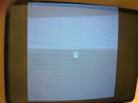
IMG_3921 (1).jpg

What this shows is a pattern of stripes every three lines. The pattern is stable if I match the frequency ratio exactly, otherwise it slowly processes up or down the screen. Here is a zoom of the edge:

640x480 two thirds scan rate to flyback.png

You can see there is a slight horizontal offset alongside a significant change in brightness. It turns out that if you follow the individual scan lines across the screen, you can see that it slowly gets dimmer over about 2 lines and then gets brighter over slightly less than 1 line.

Basically, as previously discussed on this thread, I think we're seeing the CRT charging and discharging. The question is what to do about it! Phase locking will keep the pattern still, but it won't get rid of it. As long as the frequencies are mismatched, there will be some lines brighter than others. It's possible this means the whole two-frequency solution is unworkable, but I wonder if there's some other way to compensate for the brightness change and/or keep the voltage more stable without hooking up a giant HV capacitor to the CRT anode.


apm

Well-known member
More like for safety reasons! The extra charge at 13kV is risky enough; finding a way to wire it up under the anode cap is doubly challenging.

Looking at the screen photo again, I do wonder whether something else is going on besides just fluctuating anode voltage. It seems like an awfully steep change in brightness. With that much change over one flyback scan line, you'd expect to see a bright-to-dark gradient from left to right on the normal display, which I've never noticed at all on any compact Mac.

 
Last edited by a moderator:

olePigeon

Well-known member
How difficult would it be to design a board that converts the relatively low TTL scan rate from a compact Mac to a more acceptable rate readable by normal VGA?  You could then take off-the-shelf CRTs and plug them in through the converter board.  Or LCDs even.  Would be kind of cool to put an orange plasma LCD into a Compact. :)


techknight

Well-known member
Doesn't some of the electron gun voltages come from the flyback secondaries? I wonder if there is a spot-killer or a G1/G2 voltage thats flyback-derived with poor or no filtering causing the interference. 

It has to be something along these lines, because you can run CRTs with flybacks that are completely different frequency patterns than the yoke. And be fine. How do I know this? Well Phillips did this in their late CRT projection sets before going away completely. They used HVG blocks instead of flybacks. it was a self-contained, self-oscillated flyback that ran on its own, separate from the yoke. 

I know this, because I had to change a few in my day. 

Oh, and the Motorola golden view VT-71 tube type antique TV sets did the very same thing. They were electrostatic CRTs, but that didnt matter. the high voltage was generated using a self oscillated design and tickler coil on the high voltage rectifier tube. 

So it CAN be done. 

 
Last edited by a moderator:

apm

Well-known member
Doesn't some of the electron gun voltages come from the flyback secondaries? I wonder if there is a spot-killer or a G1/G2 voltage thats flyback-derived with poor or no filtering causing the interference. 
True, almost all of the voltages except the video and the filament heaters come from the flyback secondaries. Two of them have some pretty significant capacitors (big electrolytics plus .01uF ceramics) but the voltages for focus and cut-off only get .01uF capacitors. I didn't notice a big variation in those voltages on the scope but I'll have to look more closely. I wonder how much variation would be needed to see such an effect on screen, and which voltages would be the most sensitive?

Two other ideas: first, perhaps there's some interference on ground causing a relative voltage change, most likely directly in the video signal which is only about 1V when it arrives at the CRT board.

Second, if it is from high-voltage, perhaps it's the bleeder resistor in the flyback discharging the CRT too quickly? I guess this seems unlikely as I thought it was supposed to act over a period of several seconds to minutes, not microseconds. Did the separate flybacks in those projection TVs have bleeder resistors on them?


CC_333

Well-known member
I kinda thought (but wasn't 100% certain) that many, if not most, modern flybacks (those from the late 80's, 90's and 2000's) had bleeder resistors for safety. Is this true?

This is a spectacular project, by the way!

c


techknight

Well-known member
Did the separate flybacks in those projection TVs have bleeder resistors on them?
Projection flybacks did have bleeder resistors in them, But they also had an HV splitter block that sat between the CRTs and the flyback, and it also had a feedback wire for regulation purposes I believe. 

 
Last edited by a moderator:
Top