• Updated 2023-07-12: Hello, Guest! Welcome back, and be sure to check out this follow-up post about our outage a week or so ago.

Compact Mac retina display

apm

Well-known member
I'm revisiting one of the "classic" goals of compact Mac hacking: changing the resolution of the internal CRT screen. I've been poking at this for a few months, and I've finally got enough progress now that I'm reasonably confident it can be done, so I thought I would share where I've gotten to so far. I'm very interested in any ideas!
 
It'll take a few posts, so apologies in advance for possibly flooding this thread. Ultimately 640x480 is nice, but my eventual goal is to get up to two-page display resolution (1152x870) on the internal screen. That resolution could be the B&W CRT equivalent of the retina display. :) More on that later. To start with:
 
Why do this anyway?
 
1. Increasing the resolution means more useful screen real estate (if you can tolerate the smaller pixels).
 
2. Grayscale mods will be easier to come by if we don't need a card capable of 512x342 resolution.
 
3. VGA or better on the internal CRT means that other boards (68k/PPC Mac or otherwise) can go in the case without needing the guts of some other display wedged in.
 
4. Changing the horizontal scan rate means we can overclock the SE/30 and still use its internal display.
 
5. Because we can. :)
 
Now I know this is a recurring topic on 68kmla, and that there have been some previous efforts, e.g.:
 
https://68kmla.org/forums/index.php?/topic/5045-mac-classic-bw-grayscale-vga-mod/
https://68kmla.org/forums/index.php?/topic/11043-vga-on-compact-crt/
https://68kmla.org/forums/index.php?/topic/19351-raspberry-piclassic-crt/
 
The basic problem is that it's pretty hard to change the horizontal scan rate on the analog board. More on the approach in the next post...
 
 
Last edited by a moderator:

apm

Well-known member
Just to collate some info scattered around various threads and documents (this may be old news-- and hopefully I have this all correct):
 
Background
 
The standard compact Mac resolution of 512x342 uses 22.25kHz horizontal sweep and 60Hz vertical sweep. 22.25kHz = 44.93us per scan line, of which 32.68us is the main scan and 12.25us is the retrace period (per the Macintosh Family Hardware Reference). I found this to be a useful reference:
 
http://www.gradllc.com/images/HORIZONTAL.pdf
 
The basic idea is that the current through the yoke determines the resolution of the screen. A B&W CRT doesn't have any "dot pitch" per se, so if our focus is good enough we ought to be able to get any resolution we want. Except for the video signal itself, most of the voltages on the CRT are effectively DC, which is also convenient.
 
So if we want higher resolution, we need to figure out how to drive the yoke faster. To get to VGA, we need 31.5kHz. To drive a two-page display signal, we'd need about 68.5kHz. The vertical refresh for some of these resolutions may be higher too, but that's a much easier problem and can already be done with the onboard circuitry with just a few tweaks.
 
The big problem is that the horizontal yoke coli and the flyback transformer are part of the same resonant circuit, which is tuned to 22.25kHz and really doesn't like to run at any other frequency. There are a few components you can tweak to try to change the frequency tolerance, especially the flyback capacitor (C4 in the Plus, C12 in the SE series), but as techknight found in a much earlier thread, the performance still won't be very good.
 
Measurement
 
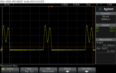
The current through the yoke is a sawtooth, but that's hard to measure directly without expensive equipment. instead, I took some measurements of the voltage on C4 on a Plus. What we expect to see is 0V for the main scan period then a big spike during the retrace period where the energy in the coil gets transferred to C4, while the beam is flying back from the right to left part of the screen. Here's what I found:
 
plus_sweep_c4_3.png
 
The flyback period is actually only 9.1us, even though the horizontal sync signal is low for 12.25us. But this is what we'd expect from a circuit like this. The retrace needs to be completely done before the HOT (Q3 on Plus, Q2 on SE) turns back on or the magic blue smoke might get out. The max voltage here is 168V, compared to a max rating of 400V for the transistor.
 
One thing that is odd is that the retrace is not a clean half-sine, but clearly shows two different frequencies superimposed. (This turned out to have interesting implications... more on that later.)
 

apm

Well-known member
Changing the scan rate of the analog board seems unlikely to work, and definitely won't get anywhere near 68kHz, so I thought it would be worth trying something different:

 
Approach
 
The way I'm working on this now is to run the yoke and the flyback and two completely separate circuits. In other words: disconnect the horizontal coil from the analog board, and then build a new circuit on similar principles to drive it. Hopefully, this means the flyback can continue to run at its usual 22.25kHz frequency to generate all the CRT voltages, while the yoke can do something completely different at whatever frequency we want.
 
Presumably the vertical sweep circuit on the analog board can still be used, maybe with small modifications. I haven't gotten that far yet.
 
Some goals
 
This approach will involve building a second circuit just to run the yoke. Ideally, I'd like to do this without requiring another Mac for donor parts. That means all the custom Apple components (yoke, inductors, transformers) should be needed in either the flyback or the yoke circuit, but not both.
 
I'm not quite there yet, but I think it will be possible.
 
Other measurements
 
I measured a few components on my Plus to get an idea of what's needed. The BOMARC schematics and Thomas Lee's Classic Mac Repair Notes also have some useful measurements.
 
Yoke resistance/inductance: vertical coil = 8.3 ohms; horizontal coil = 0.1 ohms. Horizontal coil appears to be about 80uH.
 
L2 (width coil): in its default setting, measured 23uH. I didn't measure the whole range but someone has done that on another thread (don't remember where).
 
L3 (linearity coil / saturating inductor): it was hard to get a clear measurement on this, but I think it may be around 12uH. It may be less.
 
The capacitors measured reasonably close to their rated values. C4 on the Plus is .027uF. The equivalent on the SE is .033uF.
 

apm

Well-known member
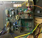
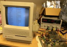
I did the early measurements on a Plus but I've done my experimentation on an SE/30 analog board. I found someone selling an analog board with a dead flyback transformer, which was perfect since I don't need it on the yoke driver anyway. Tomorrow I'll see if I can put together a useful schematic, but here's a picture in the meantime. It's a bit of a crude hack still:

IMG_2837.jpg

It takes three voltages to run the yoke board:

* 5V or the logic (U1),

* 12V for the base driver circuitry for Q2; that's the yellow wire attached to one end of R17 which has been lifted from the rest of the board

* A higher voltage, value TBD, to drive the horizontal coil itself. This will be instead of the step-up circuit involving the flyback transformer, CR3 and C13. That voltage comes in on the orange wire behind the yoke connector.

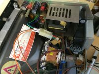
In the above photo the yoke is hooked up to the board for testing. (The blue wire is connected to the collector of Q2 for monitoring the voltage during retrace.) Eventually I split the horizontal and vertical coils, leaving the vertical coil connected to the analog board and running the horizontal coil to the modified yoke board:

IMG_2838.jpg

More later...


apm

Well-known member
So the plan is to disconnect the horizontal coil on the yoke from the main analog board and connect it to a new drive circuit which does the same thing. The first goal is just to get a decent image on the screen with these two separate circuits, which should prove the concept. Then it will be a lot easier to change the yoke driver, because all the flyback transformer circuitry will be eliminated.

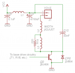
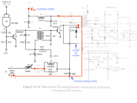
Here's the schematic of the yoke driver made from a modified SE analog board.

se30-yoke-drive.png

An here's how the modification works on the board-- greyed out components were either removed or are now unconnected, where red is for new connections. (C12 is wrong in the image below-- it should be .033, not .003)

se30-yoke-analog-mod.png

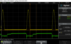
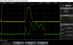
For testing I drove it with a signal matching the frequency and duty cycle of the logic board HSYNC. Here's a plot of the result, powered from Vcc = 20V. Green is the voltage at the base of Q2, yellow is at the collector of Q2.

Q2C_yoke_20V.png

The height of the yellow pulse scales linearly with the supply voltage (about 230V here). Without the flyback it's a much simpler circuit, and now we get a nice clean half-wave rather than the ringing waveform in the full analog board circuit.


apm

Well-known member
The first power-up test! For now, the same HSYNC signal drives both circuits.

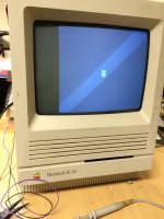
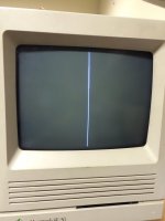
Powering up the Mac without the horizontal coil attached, of course the result is a bright vertical line on the screen. Then bringing up the voltage on the yoke driver circuit, the display gradually widened until at about Vcc = 14V it looked like this:

IMG_2841.jpg

Well it's a start. The good news is that the display is clearly visible. The bad news is (1) it's much too tall, with the image extending off the edge of the screen, (2) it's out of focus with pin-cushion distortion, and (3) it's shifted over to the right.

Both (1) and (2) are results of the same thing, namely that the HV to the CRT is reduced from disconnecting the yoke. Lower HV = easier to deflect the beam = picture too tall, and all the other flyback-produced voltages are off as well. This wasn't a surprise since the yoke stores a substantial part of the energy in a flyback circuit.

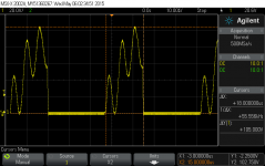
So most recently my task has been to get the HV back to its original level, without needing an extra "dummy" yoke stuck inside the case somewhere. The first start, as I think it also was for techknight's VGA experiment, was C12. Here's what that signal looks like without the yoke:

C3_without_yoke.png

This is one unhappy HOT! The retrace is much too slow, so Q2 turns on before the retrace has finished. This is the kind of thing that cooks transistors over time.

In theory the speed of the retrace should be proportional to sqrt(L*C) where L is the inductance in the system and C is ostensibly C12. So by making C12 smaller, the whole thing should respond faster. Turns out that doesn't work. Here's 10nF instead of 33nF (green plot is the one that matters):

C12_10nF_no_yoke.png

The retrace pulse doesn't actually get any faster at all! All it does is make the high-frequency ringing get a little higher. This was a surprise. I wondered if some other capacitor is setting this time constant, but after probing every pin on the flyback transformer, it's pretty clear that the other capacitors are all simple DC blockers or filter caps.

The only conclusion I can think of is that we're looking at the intrinsic winding capacitance of the flyback transformer itself. In other words, no matter what goes in C12, this circuit won't get any faster without the yoke attached. This may be one reason flyback transformers are only rated for certain frequency ranges.

The question then is what can replace the yoke...


apm

Well-known member
Finding a yoke replacement is tricky because it needs to handle quite a bit of current, at least several amps. My candidate replacement was Vishay IHA-305, a 100uH inductor rated at 4.2A. It has a DC resistance of 0.07 ohms so it's not far off from the original yoke itself.

The yoke coil measured around 80uH and the width coil just over 20uH, so I connected the new inductor to replace them both. This frees up the width coil to be used in the yoke driver circuit. Now powering up the Mac, the vertical line is sharper, brighter and about the right size:

IMG_3648.jpg

That's a good sign! The signals on the analog board also look normal again. So now bringing the voltage up on the yoke driver circuit, the image starts to emerge:

IMG_3643.jpg

IMG_3644.jpg

Except for the horizontal offset, it looks great. (The diagonal stripe is the usual camera artefact.) It's even in good focus without touching any of the adjustments.

Now that the HV is back to normal levels, it takes a larger supply voltage to get enough width on the screen. The adjustable power supply I was testing with maxes out at 20V, which is what produces the second image above. The current consumption is about 350mA = 7W to drive the yoke. Since the transistor shouldn't be absorbing much at all, it stands to reason that most of that gets dissipated in the yoke itself. I'm not about to touch it when it's running to see if it gets warm though!

On the other hand, the 100uH inductor does get quite warm-- not burning hot, but hotter than I'd like to run it with the case shut. I may have to look for an even higher-current replacement.

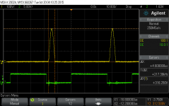
And here's what the pulse on the yoke driver circuit looks like now. I replaced C12 in that circuit with a smaller capacitor for testing (well okay, I've temporarily lost the original C12 somewhere in a pile of parts... :) ).

Q2C_yoke_20V_C12=25nF.png

Point is, the pulse is narrower, just 4.6us. That's actually really good news because it means that this yoke should be able to handle much higher scan frequencies where the retrace period is shorter.

The next step is to fix the horizontal offset. It could be from DC current but more likely it's just about the timing of the sync signal versus the video. (This is how horizontal centering is adjusted on the later Classic analog boards.)

That's where I've gotten to for the moment. Now obviously I haven't actually changed the screen resolution, which is the whole point. But between the yoke and the flyback transformer, the latter is clearly the more temperamental part to deal with. Now that they're decoupled, it should be a more straightforward path to driving the horizontal deflection coil at whatever frequency we want.


techknight

Well-known member
So your whole point to this is, separating the Flyback so that it can be powered from a free-running oscillator? Maybe phase-locking it to the yoke frequency to avoid any noise/beat artifacts? 


apm

Well-known member
Yes, that's the plan. From everything I'd read and tried, it just seemed unlikely that the flyback circuit could be pushed far enough off frequency to support any other useful resolution. So instead, decouple them.

It will be interesting to see what kind of intermodulation artifacts might pop up. Hopefully the anode and other CRT voltages don't change much over a cycle. Phase-locking is a really good idea. Maybe 3/2 ratio for VGA, 3/1 ratio for a two-page display resolution?


techknight

Well-known member
I know, I tried. If you go further past the 22Khz mark, it causes lots of linearity issues in the horizontal. Thats leaving the circuit stock with no changes. 

The vertical circuit, no problem! Horizontal, Nope. 

However, I was able to get grayscale from the original video amp circuit, even though technically its not supposed to. Just couldnt increase the resolution. This is of course with the logic gate out of circuit (cant greyscale through a digital gate). With an inverting unity gain op-amp.  

 
Last edited by a moderator:
techknight

Well-known member
Oh BTW, The flybacks used in these macs. at least the earlier ones anyway, were technically only designed for 15Khz operation. for composite NTSC stuff. 22K was really pushing it. Those flybacks were used in Wyse terminals, security monitors, etc.. All 15Khz NTSC. Like the Apple II.

Yes, you really need to phase lock the flyback transformer at the very least. Use some dividers or something, PLL lock it to the sync frequency. If you dont, youll get barkhausen distortion in the raster. Which is bad. This is due to the CRT Charging/discharging at a different phase than the scanning and retrace. 

 
Last edited by a moderator:
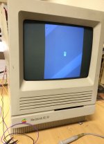
Trash80toHP_Mini

NIGHT STALKER
Fascinating, watching with great interest! Not to get too far ahead of things, but how do you intend to produce a higher res image? VidCard in an SE/30?


apm

Well-known member
Good thought on the phase-locking techknight. I just did a quick test running the AB from a free-running oscillator at (approximately) the same frequency and duty cycle, while driving the yoke from the actual HSYNC signal. The result isn't terrible, but there is a faint vertical ripple that passes periodically through the image from left to right, maybe only 1mm but noticeable because of the motion.

Given that there's not too much distortion of the image otherwise, it makes me think that any reasonable phase locking strategy may be good enough. Given what the flybacks are rated for, one interesting possibility would be to move the flyback frequency downward (say 15-20kHz) if that produces an easier phase lock. On the other hand, that might require reducing the drive voltage or it could fry something. Has anyone tried NTSC scan rates on this circuit?

jt, the plan is to get an SE/30 video card eventually. Recently I bought an SE with a Radius TPD card which I was hoping would be my first testbed, but sadly the card doesn't seem to work. Here's the TC thread about that: https://www.thinkclassic.org/viewtopic.php?id=642

Another idea would be to overclock the SE/30 and/or hack the video circuit, which conveniently is a bunch of discrete components. I think the amount of onboard VRAM might support 640x400 at 1 bit. But I haven't really thought that through yet. One hack at a time. ;)


Trash80toHP_Mini

NIGHT STALKER
Hiya, you haven't posted enough either place yet for me to recognize your username, I'm really bad at names. But I should have twigged to your posting style and the SE/TPD hints! I've got the resolution timing worksheet (spreadsheet) from whoevertheorganizationis that does the resolution standards when and if that time comes. ;)


Gorgonops

Moderator
Staff member
Another idea would be to overclock the SE/30 and/or hack the video circuit, which conveniently is a bunch of discrete components. I think the amount of onboard VRAM might support 640x400 at 1 bit. But I haven't really thought that through yet. One hack at a time. ;)
It looks like the SE/30 has 64k of VRAM, which I assume it splits into two video pages? (Too lazy to look it up, but basing that assumption on how the previous compact macs offered two pages, a feature rarely used on the 128k model, of course.) If you could use it all for one page that's 524,288 potential B/W pixels. Best fit for that would probably be that 832x624 video mode that Apple used on their midsized monitors, at 519,168. A possibly intimidating thing about that is the pixel clock would be about three times higher for that resolution than stock, so even if there weren't some software-level deal killers (IE, compatibility issues from losing the second page, etc) the stock hardware would probably need some serious tweaking to go that fast.


apm

Well-known member
Yes I'm pretty sure that's right. 640x400 = 32,000 bytes, so two pages would fit. The pixel clock would need to be 23.3MHz to get that resolution at 60Hz. I wonder if that's within a possible overclocking range? Maybe with a socketed board with faster CPU installed?

Beyond that, you're right, the changes would become so extensive that it would be much easier just to get a video card. Which might be the better plan anyway...


Gorgonops

Moderator
Staff member
Again, I don't have an SE/30 technical manual handy, but are you certain the video output and the CPU/system clocking are (or necessarily have to be) synchronous in the SE/30? Certainly not saying they're not, I honestly have no idea. I suspect there would be multitudes of fallout from simply "overlocking" the entire board; at the very least I imagine the disk controller and the serial interfaces would no longer work properly. The Motorola 68000 series, particularly the later models (68020 and up) use some sorta-complicated bus contention signals to mediate access to RAM so even *if* the pixel clock/VRAM timings are directly slaved off the same crystal that the CPU/bus clocks are derived from it would probably be *possible* at least to sever it and drive the video section off a different clock, although doing so might require some changes to the memory controller in the system... which is suddenly turning into a really ugly set of possibilities.

Honestly I have to wonder if it would actually be "more reasonable" to build from scratch a single-bit PDS video card with, say, 128k of RAM (Which would let you push resolutions as high as 1152x864-ish) than trying to hack what's there. In principle such a card should be "pretty easy" from a design standpoint, since the SE/30's PDS dispenses with the need to do Nubus arbitration, but from a practical standpoint the speeds involved put it into the "iffy" category for a home build. Just spitballing you could, for instance, use something like a Propeller MCU to generate the video timings/coordinate a couple binary counters to behave as a CRTC video address generator and implement the rest of the card with little more than a couple high-speed SRAMs and a shift register. Then you'd just need to write a driver for it and embed it in a ROM per how PDS cards do their magic and you're off to the races.


Trash80toHP_Mini

NIGHT STALKER
16" Mac Resolution is readily available on the RCPII/IIsi at 8 bit. I know someone who literally HACKED OFF the FPU end of the card to get it to fit into the SE/30. TPD would be a trip, but actually reading anything splayed across that diminutive diagonal would be kinda hard on the Mk. 1 RETINAS. 800x600 is tiny on that CRT size and 16" is a non-trivial DPI increase over that.


techknight

Well-known member
Well we have that IIsi hack thread, where the IIsi video card can fit in the SE/30 with some length hacks. 

So if you can get the internal monitor running at a higher resolution, than that card would perfectly. 

 
Top