• Updated 2023-07-12: Hello, Guest! Welcome back, and be sure to check out this follow-up post about our outage a week or so ago.

Compact Mac retina display

apm

Well-known member
After a long hiatus, I'm going back to this resolution-changing project armed with a new approach. I've established (as techknight and others have found) that the flyback transformer on most of the compact Macs can't be run at VGA or higher resolutions -- no matter what external capacitor is used, it just won't "fly back" fast enough at the end of each scan line.

Approach #1, described earlier in this thread, was to use two different analog board circuits, one for the flyback and one for the yoke. That sort-of worked. Now approach #2 is to retry the whole thing using the Classic II analog board (also found on late-model Classics). This board uses a totally different horizontal circuit with a totally different flyback transformer:

View attachment 13792
In this thread, I posted a little more about what I discovered about this transformer. Meritron appears to make a lot of transformers to this form factor, all of which have similar part numbers, but are not in fact the same part inside. So it's an open question of whether this transformer will work at higher frequencies. However, first indications are encouraging:

CL6 HOT output.png

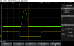
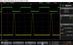
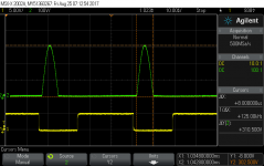
The image above shows the voltage pulse on the collector of the HOT (QL2, an IRF740 MOSFET). This transistor is hooked up to the primary of the flyback transformer and to the capacitor CL6 which should set the speed of the flyback pulse. Here we see a pulse of 316V which lasts for 8us. Compared to the earlier model compacts, the pulse is much cleaner -- a clear half-sine instead of the ringy mess you find on the older circuit.

To get this board operating at VGA resolution, that pulse needs to last closer to 5us. But for the same screen width, there will be a similar amount of area under the curve, which means shortening the pulse also raises the voltage. So the next steps will be (1) to replace the IRF740, which is rated at 400V, with a part that can withstand higher voltage, and (2) to replace CL6 with a smaller capacitor to see if the pulse can be sped up. From there I'll see how it runs at higher frequencies.

More details soon, hopefully.


techknight

Well-known member
I am surprised they are using a MOSFET in the horizontal output section, I almost never see that. It would be better to go traditional and use a standard bipolar NPN transistor with built in damper diode. I guess the good thing about a mosfet, you dont need a drive transformer. :)

you could get away with a good old classic 4426/4427. (thats what I used to use in my old class D designs back in the day.)

 
Last edited by a moderator:

apm

Well-known member
Yes I'm sure it must be because using a MOSFET saves the cost and complexity of the base drive circuit. Even the early Classic analog board uses a MOSFET for the HOT (IRF640 in that case), while the earlier compacts use a BJT (BU406) with a transformer. Since the Classic was designed for low cost above all else, I have to assume that the economics of transformers vs. active devices shifted between 1983 and 1990.

It does seem to be hard to find MOSFETs rated much above 650V drain-source voltage. It looks like on a lot of horizontal circuits, including the early compacts, the HOT drives a different tap than the flyback capacitor is connected to. I assume that means the voltage at the HOT is only a fraction of the voltage that appears at the capacitor. For example, in a 9" VGA monitor I disassembled, the HOT is only rated at 200V, but the capacitor is rated up to 630V. They're connected to different taps.

Unfortunately, the flyback transformer in the late-model Classic doesn't appear to have extra taps, so the HOT will just have to deal with whatever pulse appears on the capacitor. I'll stick with MOSFETs for now, unless you can suggest a good generic base drive transformer? :)

 
Last edited by a moderator:

K55

Well-known member
I've had good luck with the IP series of mosfets from infenon, you can get a 800V 5A transistor for a little under a dollar these days.

I mean you'll probably need a huge ass heat-sink but eh, the gate capacitances and Rds resistances are much, much lower than the late 90s :approve:


Trash80toHP_Mini

NIGHT STALKER
AM caffeine deprivation mode insanity for the day: been poking around in my old SuperMac Spectrum24 project and had a thought:

There's a slight chance we could crack this problem from the opposite direction, at least for grayscale at standard resolution. The software for this very early NuBus card calculates the oscillation required by its hardware to run any resolution at any refresh rate within the limits of its 3MB of VRAM, presumably for compatible crystal specs..

WAG: working backwards from the SE/30 CRT input spec, working out a video card's output timing spec ought to be easy enough.

Insane part:

Development of a video card for the SE/30 68030 "PDS" wedged into the system at the CPU socket level.

_ by removing the Video ROM of the SE/30, the video subsystem is deactivated and its interrupt for PseudoSlot $E is freed for use.

_______ IIRC tk mentioned possible complications elsewhere in the remains of the video subsystem . . . whatever.

_ direct access to the interrupt for $E at the CPU socket negates the problem of it not being present on the 030 PDS slot.

_ using $E for a video card preserves use of the interrupts available on that slot for max conventional expansion capability.

Coffee is kicking in so I've lost fuzzyfocus on this notion while digging up relevant lines of research:

_ design reference for Grayscale neck board development is well documented

_ the Toby hack was inspired by discovery of  a reference design for discrete, off the shelf component implementation of a video card

_______ aside from DeclROM, only two ©Apple ICs are present, they look to be NuBus MUX components and if so, irrelevant

_ the SE/30 socket version of the PowerCache offers reference design for 030 socket buffering requirements.

_ all aspects(?) of Video Driver development is conveniently documented in DCaDftMF

Now that I'm waking up, I'm wondering if this is relevant to your Retina project, but I'm hitting the button anyway. :-/


apm

Well-known member
I've had good luck with the IP series of mosfets from infenon, you can get a 800V 5A transistor for a little under a dollar these days.

I mean you'll probably need a huge ass heat-sink but eh, the gate capacitances and Rds resistances are much, much lower than the late 90s :approve:
You're completely right. Looks like I was incorrectly filtering for MOSFETs with < 100mOhm on resistance, when I meant to be looking for < 1 ohm.

For example, the Infineon IPP80R280P7 has better specs than the IRF740 in essentially every way: voltage rating, on resistance, gate charge. I guess it shouldn't be surprising that the core technology of switching power converters has improved just a bit in 20 years!


techknight

Well-known member
they also explode alot easier and more often than the 90s. 

I honestly think they over-rate these transistors IMHO, especially in Class D circuitry. 


apm

Well-known member
Well I've changed the IRF740 for an IPP80R280P7 (800V rating), and the Mac still works. No change in picture or in signal at the gate. Next up, messing with the flyback capacitor and seeing what happens to the retrace time and the secondary voltages.


apm

Well-known member
More progress: on the late Classic analog board, changing capacitor CL6 does indeed change the retrace time in the way I would expect. Here it was with the original .028uF capacitor:

View attachment 14058
And here it is after replacing CL6 with .018uF:

CL6 = .018uF.png

Theory suggests that reducing CL6 by a factor of N would reduce the retrace time by a factor sqrt(N) while increasing the peak retrace voltage by sqrt(N). What we see here pretty much matches that on both time and voltage. I tried CL6 = .022uF as well and also got results that match the theory.

I also find that the secondary flyback voltages as measured on CL2 and CL5 increase by the same ratios -- i.e. smaller CL6 = higher flyback secondary voltages. That has the side effect of making the picture smaller (because the anode voltage is higher); the other voltages to the CRT can be readjusted by the pots on the analog board. However I'm not sure at what point a higher anode voltage goes out of spec for the CRT.

Anyway, here's what this all means for resolution changing:

The retrace time on the analog board as it stands is 8.0us. According to the VGA spec, it can be no more than 5.7us (sync pulse plus back porch). That's a reduction of sqrt(2) meaning we need to cut the value of CL6 in half: .014uF. That's not a standard value, so we could choose .012uF instead. On that basis, I'd expect a flyback pulse of 473V. The newly replaced HOT can handle that, but it turns out diode DL5 (BYV26B, rated at 400V) also needs to be replaced with a higher-voltage part. The secondary voltages would be -186V and 1130V; I believe those are still within the rated limits on the relevant parts.

But it would be better if the flyback secondary voltages didn't have to keep increasing. So I may try to find some way to avoid having all the energy of the retrace making its way through the flyback; maybe adding another inductor somewhere around the primary? I still need to think about how that might work.


techknight

Well-known member
You dont want to run a 9 Inch CRT past 13.5KV if you can help it. Any more, you will get arcing, or worse, X-ray production!

If the secondaries are increasing, Why not drop the incoming B+? 

You have to adjust the B+ all the time for different frequencies. For temporary sake, Isolate the sweep B+ away from the main power supply and use a bench unit. 

 
Last edited by a moderator:

apm

Well-known member
Using a bench unit for B+ was my plan once I start changing frequencies.

The problem is that B+ controls both the secondary voltages and the screen width. On the late Classic board there's no adjustable inductor at all, only a changeable B+ for controlling width. Higher resolutions will actually need even more B+ to reach the same width at higher frequency. Looking at it another way, once you get to the end of a scan line there's a certain amount of energy stored up in the flyback and yoke, which is directly related to the screen width. If you want to discharge it faster, the voltage has to go higher.

How do multisync monitors get around this problem?

 
Last edited by a moderator:

techknight

Well-known member
I know with multisync monitors, they have relays that cut certain circuits in and out, but more importantly, it has a sync microprocessor. it shapes the drive pulses digitally, and stores the width, height, keystone, pincushion, etc for each and every supported frequency. Also the B+ is variable digitally in those units as well.

Also sony multisync monitors, they split the flyback and yoke circuits completely. there are 2 HOTs. The conclusion here is the flyback is probably fixed-frequency which is phase locked to the yoke frequencies. 

the last of the CRT projection sets were HD, and a grand majority of those were 2 separate circuits as well. Then the cheaper ones had a single output, but the deflection circuit was designed to be fixed-frequency and it used digital up/down scaling like LCD sets today. 

 
Last edited by a moderator:

apm

Well-known member
So, some voltage measurements on changing the sweep frequency. We start with CL6 = 0.018uF (smaller than the factory 0.028uF), and with the HOT and the flyback diode both replaced with parts tolerant of 800V spikes.

I measured three flyback secondary voltages: across CL1, CL2 and CL5. CL1 was unchanged at 14.8V regardless of frequency. "Flyback pulse" is the peak voltage of the flyback primary pulse across CL6 during retrace.

Frequency   Flyback pulse  CL2   CL5

22.25kHz    398V           -155V 958V
23.0kHz     382V           -150V 925V
24.0kHz     366V           -143V 881V
25.0kHz     354V           -137V 843V
26.0kHz     338V           -131V 806V
27.0kHz     326V           -125V 773V
28.0kHz     314V           -120V 741V
29.0kHz     302V           -115V 711V
30.0kHz     289V           -110V 683V
31.0kHz     281V           -106V 656V
32.0kHz     271V           -102V 631V
33.0kHz     261V           -98V  609V
34.0kHz     253V           -94V  585V
35.0kHz     245V           -91V  566V
36.0kHz     237V           -88V  544V
 
For reference, the nominal values with the original parts and original frequency were 310V, -122V, 740V. That's pretty much equivalent to what I get a 28.0kHz with the smaller CL6. So the conclusion seems to reasonably be that a smaller CL6 and a higher frequency work happily together.
 
Based on the above calculations, I expect CL6 = 0.014uF would be right for VGA, and 0.011uF for the Apple 13" resolution (35kHz scan rate).
 
As I increase the frequency, the picture gets both narrower, taller and dimmer. That's what I would expect. Faster scan = less time to sweep left-to-right, which shrinks the picture horizontally. But it also means lower high-voltage, which reduces brightness and makes the vertical deflection more effective.
 
So far, all signs point to higher resolutions working just fine on this analog board. The next step is to try an actual VGA signal, and then if the picture can't be made wide enough, figure out how to boost the B+ voltage.
 

apm

Well-known member
Finally, over 5 years after I started this thread, here we are: VGA 640x480 in grayscale on a Classic CRT!
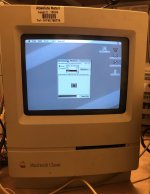
IMG_8828.jpg

The above image is displayed with an original CRT and an original (modified) analog board, with a replica Xceed CRT neck board for grayscale. The display is coming from an LC II but could be any VGA source.

A synopsis for those just joining this thread: the goal is to increase the resolution of the compact Mac screen from 512x342 to 640x480 (or higher). There have been several nice hacks of the display before, but they usually involve replacing the CRT or at least putting in the guts of another monitor like a 12" Apple Monochrome Display. Here, I'm trying to increase the resolution using the existing CRT, existing analog board and existing flyback.

It turns out, for reasons explained earlier in the thread, that it's much easier to modify the late-model Classic analog board (used in the Classic II and later builds of the Classic) than any of the earlier compacts, because the late Classic board uses a different and more flexible flyback transformer.

The challenge in a nutshell is that increasing the screen resolution means increasing the horizontal scan frequency from 22.25kHz in the original to 31.5kHz (VGA) or higher. The horizontal sync is used to drive the flyback which generates all the voltages to the CRT, and the circuits in the compact Macs are very much not multisync: they are finely tuned to operate at exactly 22.25kHz and VGA is a long way from that.

The specific barrier to higher horizontal scan rates is the retrace time -- how long it takes the beam to go from right to left of the screen. This is ~8us on most compacts, but for VGA it needs to be 5us or less, or you'll end up with foldover on the left part of the screen.

Shortening the retrace time inherently means increasing the retrace voltage pulse (see earlier plots in this thread). That pulse is what powers the flyback and generates all the CRT voltages. Increase the pulse and all the other voltages go up with it, which is bad. Hence the problem changing resolution.

Anyway, I found a working solution. It needs the following large components:

1. Classic or Classic II with late-model analog board (logic board is not used)

2. Micron Xceed replica grayscale CRT neck board - I used a PCB from @Bolle.

3. Benchtop power supply capable of generating 45V at 0.3A. Highly recommended that this is adjustable so you can ramp it up slowly for testing.

4. VGA signal source - I used an LC II, but it could be anything

These are the modifications to the analog board (referring to BOMARC schematic):

1. Replace capacitor CL6 (originally 0.028uF) with 8.2nF, rated at 600V or higher

2. Replace MOSFET QL2 (originally IRF740) with IPP80R280P7 or similar (rated at 800V)

3. Remove voltage regular IP2 (LM317) and diode DP13. The 45V benchtop supply should patch into the output of IP2 (pin 2). It may also be beneficial to replace CP11 (220uF/50V) with a part with a higher voltage rating, though I haven't done this.

4. (This is the part that took me the longest to figure out) Cut the trace going to pin 4 of the flyback transformer (which connects it to the now-45V supply). Wind 16 turns of wire around the core of the flyback (see photo) and solder across the trace you just cut. Starting from the side of the trace connected to the power supply, the windings should go counterclockwise around the core, finally connecting to pin 4 of the flyback. More on this below.
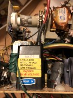
IMG_3756.jpg

5. HSYNC and VSYNC need to be supplied by the external VGA signal. At least for HSYNC the sync pulse needs to be lengthened to >10us for the analog board to be happy with it. This can be done with a 74LS123 one-shot multivibrator (I also use a similar circuit for VSYNC). These connect to pin 5 (violet wire) and pin 4 (grey wire) of the cable that goes to the logic board.
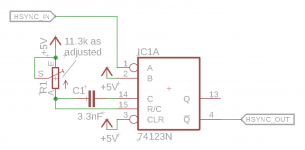
Screenshot 2020-12-28 at 00.45.44.png

6. The CRT neck board is soldered to the analog board in the Classic. It needs to be desoldered to attach the Xceed neck board. I found it helpful to desolder the wires at the neck board side and attach a 12-pin Molex connector like on the SE/30 analog board, so that I could use the existing cable harness I had for the Xceed. The VGA video signal bypasses the analog board entirely and goes straight from the HD15 connector into pin 6 on the Xceed board.

7. Without the logic board, there's no brightness control. I replaced it with a signal generator but a constant 5V source should work fine. It goes to pin 9 (blue wire) of the cable assembly that goes toward the logic board. 

Once all of that is done, it can be tested and adjusted. For testing, I usually bring up the video signal and 5V to the 74LS123, then I power on the Classic, then finally I gradually bring up the 45V supply voltage to the flyback. It's important the sync signal stays stable while the circuit is powered. I blew up a couple MOSFETs when I turned off the 5V supply and the MOSFET stayed on too long, resulting in an enormous voltage spike when it finally turned off.

To get the picture mostly centred, turn PL3 (H. Center) control to its minimum value.

Even at a standard resolution, the Xceed board needs some adjustment. With the brightness all the way up, I adjusted PL2 (Cut-Off) on the analog board and the trim on the CRT neck board until I was happy with the brightness and linearity of the grayscale. Then I adjusted the focus (PL1).

Why it works:

Reducing CL6 from 28nF to 8.2nF reduces the retrace time to 5.0us. This is short enough to fit between scan lines at VGA, where there is 6.3us from the end of the visible part of one line to the start of the next.

Because the horizontal frequency is higher, the beam needs to move faster across the screen. That means we need a higher drive voltage than before. In the original Classic the flyback is driven from 30V, but I found 45V produced the right width of picture.

The result of the above will be a much higher retrace pulse: 486V instead of 310V. That would blow up the original QL2, which is why we substitute the higher-spec part.

Now the big problem is that all the flyback secondary voltages are directly proportional to the retrace pulse. We really don't want everything to be 50% higher! I stumbled around on this for a while, before I realised that we could change the turns ratio of the transformer just by winding some extra turns around the core. Basically, we want more turns on the primary side. I arrived at 16 turns by trial and error. I haven't tested this on other machines, and I don't know if it is sensitive to how tightly the turns are wound or what gauge of wire is used. Based on my measurements I expect 16 is a minimum number of turns rather than a maximum.

The 74LS123 is needed because the Classic HSYNC circuitry filters out signals that don't stay low for at least ~10us. Without it you'll get no retrace pulse at all. Also we need QL2 to stay turned off for the entirety of the retrace time, which is actually a bit longer than the VGA sync pulse.

With all of these modifications in place, I measured the following voltages:

Pulse at CL6: 486V / 5.0us [original: 310V / 8.0us]
CL1: 13.0V [original: 14.7V on my set; BOMARC says 12.6V]
CL2: -131V [original: -123V on my set; BOMARC says -109V]
CL5: 786V [original: 740V on my set]
HV: estimated at about 14kV [BOMARC says 13kV]

The video signal is fairly clean though it looks like there's a possibility of slight ghosting because of an impedance mismatch between VGA and the Xceed board. That needs further investigation, but the good news is that the levels match out of the box. My modification drives the Xceed video amplifier with a 45V supply rather than 30V, but I haven't seen any adverse effects of this.

Next I need to tidy this up a bit and try to reduce the dependence on external supplies (e.g. find a boost converter for the 45V). I'd like to get this into an SE/30, but its flyback transformer is much less flexible. So one possibility is to design a hybrid board where the horizontal circuits of a Classic could be transplanted into an SE/30 form factor.
scope_1.png


james_w

Well-known member
You’ve been working on this most of the time I’ve known you. So exciting you’ve succeeded!

also that’s a very clear and in-depth explanation - thanks!

I doubt I’ll be attempting to duplicate your efforts any time soon but I’d love a hi-res grayscale compact Mac one day :)


EmNem543

Well-known member
How difficult do you think it would be to create a Display Driver to take an input from a modern computer and output an XGA (1024 x 748 4:3) or WXGA (1152 x 768 3:2) resolution on that little 9" CRT? At that point, you would have the pixel density of a modern display and a useable resolution (in grayscale of course). I've tested both Mac OS (latest) and Windows 10 at those resolutions and they are perfectly usable for day-to-day tasks. I think it would be really cool to have some basic kit to convert a Compact Mac and put something like an M1 Mac Mini inside and use the original display without permanently modifying anything.
 
Top