• Updated 2023-07-12: Hello, Guest! Welcome back, and be sure to check out this follow-up post about our outage a week or so ago.

Bombed Macintosh Classic Failing to start after attempted fix + recap

Kouzui

Well-known member
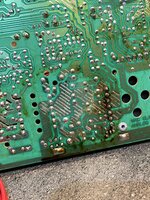
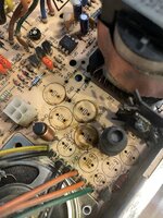
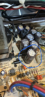
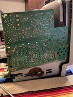
Well, I safely discharged the CRT, took out the analog board, and... eugh, yeah, that's a lot of corrosion Pretty sure it's mostly from the battery, but there's plenty of capacitor goop I can see between the caps on the board, too. Looks like a definite analog board recap. Welp, guess I'm paying Mouser again.

badleak.jpg
Edit: Bonus carnage
carnage.jpg
 

Kouzui

Well-known member
I'll take a look at that, might need it because I remember the last time I had to mess with larger thru-hole components, and that was a royal PITA with just an iron and wick.
 

falen6

Well-known member
I use beed tants because they are so much easier to solder on - I never liked those flat , rectangular tantalums because you cannot see the connection underneath.

If it was me i would take off all the tants again and clean up all the pads with some soldering brade - get rid of all the old solder

only then you will be able to see if everything is good , with no shorts and only then you can move forward.

Just to remove the possibility of shorting out a pad when resoldering the caps it might be a good idea to cut some short bits of wire and solder them to the caps as legs , so you can solder the tants back on and clearly see the state of each pad after the soldering job.

Whenever you are trying to find broken traces you just simply cannot tolerate the slightest possibility of a short from soldering - you could spend dozens of hours trying to find the illusive broken trace , only to find much later it was a bad solder connection ........... we have all been there


1 - remove all the tants
2 - clean off all the old solder from the pads with brade ( use a good flux to get it all off - you want to be left with shiny clean pads )
3 - solder some short bit of wire as legs to the tants ( cut them all the same length , 2cm or something )
4 - solder them back to the board.( dont use loads of solder - less is more with soldering - just enough to secure the connection - and remember not to keep the heat on the pads for too long as that will weaken the glue between the pad and the board and you will end up lifting a pad)

if you do this you will be able to eliminate the possibility of a soldering mistake and focus on finding the problem

what ever happens after that you will have one cool looking board with tants floating above the board
 

davidg5678

Well-known member
Good work on the battery-damaged logic board! I did something to a similar PCB a few years ago, and almost got it working again. (You've reminded me I should dig it out and play with it again :).)

From your photos, it looks to me like there's a considerable amount of capacitor leakage on the analog board, unfortunately. The clicking sound probably has something to do with the switched-mode power supply failing to get started. There very well may be a short on the logic board, but I definitely wouldn't assume that this analog board/power supply is functioning correctly right now. I think you'll need to do a full recap on the analog board, and also may need to replace a few diodes or ICs that have been damaged (Thankfully, there are a few threads on this forum detailing the parts that most commonly fail on these analog boards). The capacitor fluid on the back of the PCB also needs to be cleaned off with isopropyl alcohol.

Because of the state of the logic board and analog board, I think it's going to be pretty difficult to rule out which pieces of the computer are working without having known good parts to swap with. If you can get ahold of another functioning Mac Classic (to temporarily borrow parts for diagnostic purposes), this would be extremely useful right now.

Otherwise, I think the idea of testing the components in isolation makes a lot of sense. The 12V light bulb idea seems like a good starting point.

It is possible to run the Mac Classic logic board without an analog board, but you'll need to rig up a power supply of your own; you'd also need something like the RGBtoHDMI to display video externally. This would be a bit advanced, and it would be hard to diagnose which part of your setup is working properly when you aren't yet 100% certain the logic board is functional.
 

Kouzui

Well-known member
think you'll need to do a full recap on the analog board, and also may need to replace a few diodes or ICs that have been damaged
Yup, that's what I'm going for. I haven't bought any diodes or anything yet, just caps. I have an SE and a plus, but not another Classic. The caps are coming tomorrow, and I'm going to do the lightbulb test after the recap. I have the whole thing apart at the moment so I can't quite test it now.
 

Kouzui

Well-known member
An update to this-- I bought and received both the caps from Mouser as well as the solder sucker recommended to me earlier in the thread. I will get the recap done either today or tomorrow, and then post results.
 

Kouzui

Well-known member
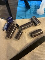
ok, now this is pretty frickin' gross. You're telling me these electrolytic fluid-soaked power cables had a short? insanity.
shitstain.jpgthebois.jpg

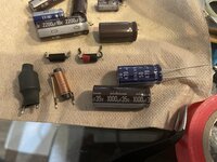
Edit: I followed the guide for which capacitors to buy from RecapAMac and, although I wasn't able to see it because of the angle, it turns out that the 470uf 50v capacitor on that guide is, in fact, a 1000uf 35v capacitor on the American power supplies. Gonna have to buy a new cap, but before I do that, does anyone have part numbers for these other bits? I took them out to clean, and since I have to buy a new capacitor anyway, if I could also pick up equivalents for these it would be nice, in case any don't work.
imposter.jpgmismatchanddiodes.jpg
 
Last edited:

Kouzui

Well-known member
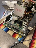
All right, I have an update. I've changed out all the caps on the analog board, installed NEW tantalum caps on the logic board, and hooked everything up.

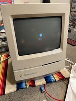
The good news: We have a chime, the display works, and something seems to be going on.

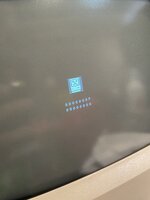
The bad news: Sad mac. Code 0000 000F 0000 000A. IIRC the 'F' codes have something to do with RAM, but I'm gonna have to see if there's info online about this one in particular.
theCode.jpgClassicSadMac.jpg
analogboard.jpgmoboClassic.jpg
 

zigzagjoe

Well-known member
Nice work! How far does it make in the boot process? It should be past the RAM test if you've got enough video to display a sad mac.

I think major error code F is a catch-all for system exceptions.... NMI button during boot would cause it to be shown for example. I believe that specific error is a "Line 1111" exception, which as far as I know means some sort of insanity is going on. Line 1111(0xF) is a FPU opcode that I wouldn't think would ever be part of classic's boot process.

Is the error code consistent?
 

Kouzui

Well-known member
Nice work! How far does it make in the boot process? It should be past the RAM test if you've got enough video to display a sad mac.
It chimes, there's a gray screen for just a fraction of a moment (visible when the display is already warm from a previous power cycle), and then the sad mac appears.
Is the error code consistent?
Yup. Multiple resets, unplugged the fan, unplugged the floppy, same result.


Also, if anyone was wondering, the short on the analog board is actually visible in my previous post. The 12v rail was arcing to ground via the speaker metal, and you can see it is corroded and melted there.
 

zigzagjoe

Well-known member
It's a bit of a long shot, but you could try re-seating the ROM chip.

Otherwise, I'm kind of at a loss as to what would cause a line 1111 emulator error as it implies for some reason executing bad code / general insanity.... I suppose you could check address lines from the CPU to ROM too.
 

Kouzui

Well-known member
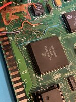
The problem might be this general area, but as far as I can tell all the traces have proper continuity (I've done quite a bit of prodding here):
hodgepodge.jpg
Specifically, it might be that one of the traces from the ROM to the CPU is messed up, if that code is indeed something about illegal ROM instructions.


I have not tried to reseat the ROM, because I lack a tool I can use to do it without damaging the pins.
 

zigzagjoe

Well-known member

davidg5678

Well-known member
Great work bringing the power supply and analog board back to life! While the computer still isn't booting, we now know most of the main components are working.

You should be able to use any modern computer and a USB to serial adapter. Something like a Unix/Linux terminal, ZTERM, or PuTTY should allow you to send and receive serial data. I've never tried out this serial diagnostic mode, but it sounds like it could be useful.

The guide says to use "9600 baud, 8 data bits, no parity, and 2 stop bits." (These are the configuration settings to use with the serial terminal program on your modern computer.)

Take a look at this guide, as it has a lot of good info about how to use a serial terminal: https://learn.sparkfun.com/tutorials/terminal-basics/all
 

Kouzui

Well-known member
You should be able to use any modern computer and a USB to serial adapter. Something like a Unix/Linux terminal, ZTERM, or PuTTY should allow you to send and receive serial data. I've never tried out this serial diagnostic mode, but it sounds like it could be useful.
Well, I've bought a USB to 8 pin mini-din adapter, and I suppose I'll give it a shot when I get that cable.


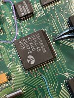
As for the pin that needs to be grounded, is it this one?:
isitthispin.jpg
If so, do I just need to run a wire from it to some ground plane?
 

Phipli

Well-known member
Yeah, I haven't got the most experience, or the best soldering iron. I'll check the tantulums but when I installed them I didn't see any bridges.
Do you have some liquid flux? Its the secret trick. Flux makes your soldering better, as if by magic.

The iron you use doesn't really matter until you try to desolder something huge or on a ground plain, like connectors. Don't try to desolder a floppy port unless you have a like, 70W iron. Sigh.
 
Top