• Updated 2023-07-12: Hello, Guest! Welcome back, and be sure to check out this follow-up post about our outage a week or so ago.

Bombed Macintosh Classic Failing to start after attempted fix + recap

Kouzui

Well-known member
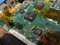
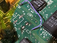
I'm working on a Macintosh Classic which has unfortunately seen the bad side of a clock battery. The damage didn't seem to be too terrible to me, but I replaced all the caps on the logic board (have not touched the analog board, and don't intend to if I don't have to). I've also repaired a few traces that I could see were broken, as well as the two diodes near where the battery was. I removed the RTC and SND chips and dipped them in vinegar/alcohol as well. Unfortunately, one of the legs came off of the RTC chip, but I tried my best to make a makeshift wire connection to the trace with what remained.

However, when I plug in the logic board and try to turn it on, it fails to start. I've attached a video of what happens when I try.

What I was wondering is: Has anyone ever seen this before? is the board dead because of the missing RTC leg? (Can provide pics if you need them, the missing leg is the one closest to the battery corner of the board, on the side with the reset buttons).

I can't find any examples of this behavior online, and I'm basically just wondering if it means it is dead for good, or if I can keep working on it to bring it back to life.
View attachment IMG_8497.mov

I should note that, when I turn it on without the logic board, the fan runs consistently and there are no strange noises from the CRT or logic board.
 

zigzagjoe

Well-known member
That is really weird. I'm wondering if you might have a short on your LB causing the power supply to rapidly cycle on and off due to overload...

if your meter reads quickly, you might try putting it on 5v and 12v rails with LB connected and seeing what you get. If your meter doesn't read so quickly, an LED on those lines instead might give enough insight. You could also try the continuity range on your meter - it may beep at first but should stop, and stabilize at at least a few hundred ohms.
 

chiptripper

Well-known member
That’s a short, yeah. Pics of the logic board would help, definitely.

The Classic is a tough cookie because cap damage can cause as many problems as a battery bomb, AND the analog boards tend to have issues too.

On that note, your AB may have cracked solder joints at the plug connectors, and some caps WILL need to be replaced. No getting around it, unfortunately. Probably not the root cause here but keep it on your radar.
 

Kouzui

Well-known member
On that note, your AB may have cracked solder joints at the plug connectors, and some caps WILL need to be replaced. No getting around it, unfortunately. Probably not the root cause here but keep it on your radar.
Damn. Alright, I'll keep that in mind. Would you mind linking a good source for how to safely discharge the CRT and which caps on the LB I need to discharge?

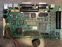
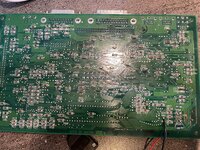
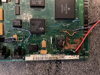
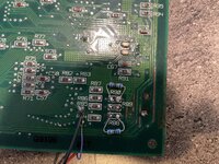
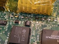
In the meantime, here are the pics of the logic board. This is after a scrub with vinegar and a toothbrush, an ultrasonic cleaning (a friend had a machine), and wiping down with isopropyl. I've tested most of the traces for continuity, and already patched the ones I found that were obviously broken. Not very pretty, but I've only done one other recap before, and never a battery bomb.

Logic_board_entire_front.jpg
Logic_board_entire_rear.jpgLogic_Board_bomb_site.jpgLogic_board_100kohm_replace.jpg
 

zigzagjoe

Well-known member
Dang... not trying to be mean here, but that solder work is a bit gnarly. The pics aren't quite good enough to tell, but I'd closely check those tantulums you soldered in. A common issue I've encountered is the solder mask on traces in proximity to the caps gets degraded by the cap juice, and you can end up bridging traces due to wide tantalum contacts (wide rectangle) as compared to the original (slim rectangle) contacts, especially when there's extra solder.

Since we suspect this is a short, next step is determining what rail(s) are affected with your meter. From there you can chase the schematics to determine which of the new caps are potentially a problem. Or, you could start pulling caps off to investigate, though bear in mind that tantulum caps don't like heat and probably should be replaced rather than re-used.
 

Kouzui

Well-known member
that solder work is a bit gnarly.
Yeah, I haven't got the most experience, or the best soldering iron. I'll check the tantulums but when I installed them I didn't see any bridges.
 

Kouzui

Well-known member
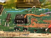
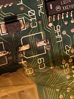
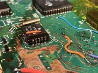
Ok, took all the caps off and took another look. I didn't see any bridges, and double checked all my trace repairs for continuity and making sure they didn't bridge with neighboring traces. Updated pics in case anyone sees anything, as well as up-close pics of the wrecked sound chip.

Believe it or not, that wire is actually connected to the stump of the missing leg. It was not easy to do. Also C6 is indeed missing most of the trace, but I had it soldered to what's left, towards the power connector.
soundchip-side.jpgc5-c9.jpgc9-upclose.jpg
soundchip-other.jpgcapsoff_C1-c4.jpgcapsoff_c3-c4.jpg


As for measuring the rail voltage, do you have a schematic for which pins I need to be looking at?
 
Last edited:

zigzagjoe

Well-known member
Oh yeah, I had a similar experience with my sound chip in my SE/30. Everybody loves carving ceramic out with a scalpel, right?

Here's a schematic to have a look at. If you're brave, you could try powering it on without the caps to see if anything changed, but I'd recommend the continuity check/resistance measurement of the various power supply rails and gnd first.
 

Kouzui

Well-known member
Oh yeah, I had a similar experience with my sound chip in my SE/30. Everybody loves carving ceramic out with a scalpel, right?

Here's a schematic to have a look at. If you're brave, you could try powering it on without the caps to see if anything changed, but I'd recommend the continuity check/resistance measurement of the various power supply rails and gnd first.
Haha, got a bit ahead of you. I did try to power it on without the caps, as I read somewhere that it was actually possible. Nothing changed, it still cycles as it did before.
Also, I meant to say pinout as opposed to schematic, since I found that schematic you linked and thought it to be a bit... involved for what I'm trying to find out. I had found a pinout on google, but the problem was, I wasn't sure which pin would be considered pin 1, since there is no color code. Fortunately that schematic does say what color the pins are, so I'll try measuring the voltage and post an update.
 
Last edited:

Kouzui

Well-known member
All right. Without the logic board in place, the +12v rail provides a consistent 11.48v and the +5v provides 4.95.
I assume that's pretty low. When I plug the logic board in, the 12v rail jumps up and down between 1v and 11v, and the 5v rail jumps between 0.05 and 1.95.

So I take it I should look into getting that CRT discharged, huh?
 

zigzagjoe

Well-known member
1687745132537.png

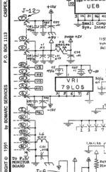
This looks to be the part you want. There's numbering on your LB you can look at, and there is a color code on it.

pin 1 (yellow) is 12v
pin 2 and 3 (orange) should be 5v
pin 8 (green) ought to be -12v.

You want to measure resistance with the board unplugged from the AB between each of these and ground, not voltage.
We know something's badly wrong on one of these rails, the question is which, then you can start investigating where that rail goes and try to figure out where the short might be. This is going to not be a fun process...
 

Kouzui

Well-known member
Forgot to check the -12v rail. It shows ~-11.48v without the LB plugged in, and between -9 and -11.48 with it.
 

zigzagjoe

Well-known member
Most likely the -12v rail is fine. Your voltages without the LB connected seem fine, not of immediate concern.

You'll need to measure the resistance (ohms) between +5v and ground, and +12v and ground. If you don't have an auto-ranging meter, start at the lowest range and step up. I expect one of those will probably show a very low resistance indicating it is the problem.
 

Kouzui

Well-known member
I expect one of those will probably show a very low resistance indicating it is the problem.
You're right, there is 300ohms of resistance on the 5v rail (both of them, FWIW). I'll start trying to figure out what that means, and where it goes.
 

zigzagjoe

Well-known member
300 ohms is fine, and it would be the same for both 5v connections (they aren't seperate rails, just redundant connections). Try checking the 12v.

By low resistance, I would expect 0 - 5 ohms. Essentially a dead short.
 

Kouzui

Well-known member
300 ohms is fine, and it would be the same for both 5v connections (they aren't seperate rails, just redundant connections). Try checking the 12v.

By low resistance, I would expect 0 - 5 ohms. Essentially a dead short.
Nothing at all (multimeter doesn't react) on +12 or -12. Also, the exact measurement I took over 5v was 302ohms, and is now 297ohms on the remeasure Not sure it makes a difference but if we're talking on the factor of only a couple ohms it might be worth pointing out.
 

zigzagjoe

Well-known member
Hmm. Those all roughly line up with expectations. On a SE/30 board, I get ~250 ohms on +5v, and various extremely high readings on +12 and -12v. So those don't sound immediately problematic. Only a very low value would be a potential issue here, +- 5 ohms on 250 wouldn't matter.

It's possible your AB is so far gone that it's freaking out with just the LB attached.... If you have a 12v bulb handy (any kind, really, as long as it is not LED), you could try connecting that between +5v and ground on the AB connector (without LB connected) as a test load.

Not sure exactly what +5v on a classic is rated for, but I'd expect it to be able to do at least 3 amps. A 20w automotive bulb (@12v) will take about 5 watts (1 amp) @ 5v, so it works for a basic test load. More would be better, but anything is a start.

If you have a 10 watt or less 12v bulb you could do the same test on the 12v rail - it should be able to do about an amp, based on SE/30.
 

Kouzui

Well-known member
If you have a 10 watt or less 12v bulb you could do the same test on the 12v rail - it should be able to do about an amp, based on SE/30.
I do actually, I have a (12 watt) Tensor lamp that takes those bulbs. I don't know how I'd go about safely connecting it to the logic board, though. Might need thicker wires than the little bodge ones I have.
 

zigzagjoe

Well-known member
I do actually, I have a (12 watt) Tensor lamp that takes those bulbs. I don't know how I'd go about safely connecting it to the logic board, though. Might need thicker wires than the little bodge ones I have.
You don't want to connect it to the LB - you want to connect it to the AB only (no LB connected) to see if AB immediately throws a fit (flicks on and off) like it was doing with the LB connected. If it does that again, then you'll have to fix the AB before doing anything more on the LB.

Honestly, as far as wire goes, just about anything would works for this load testing as long as it isn't absolutely tiny. The red wire you have near the sound chip would be fine. We don't care about the voltage drop on the wire for this test. 12 watt bulb should work for testing +12v, and it's better than nothing for testing +5v, though you really want something that can put a little more load for an accurate test.

Alternatively, just proceed with the recap of the AB. Like @chiptripper said, it's likely a source of issues. I wouldn't worry about discharging the crt if you've waited a day or so since last powering it up, or to be safe you can make a discharge tool with a small screwdriver and a resistor in the megaohms range. connect resistor to screwdriver and other side of resistor to ground on the monitor frame, then insert the screwdriver carefully (hold the plastic handle and/or wear rubber gloves!!) under the anode (suction cup looking thing) until it makes contact with the metal connector within. That's all.
 

Kouzui

Well-known member
Whoops-- I said logic board, but definitely meant analog board! I'll try that stuff tomorrow, and probably buy some caps from Mouser too.
 
Top