• Updated 2023-07-12: Hello, Guest! Welcome back, and be sure to check out this follow-up post about our outage a week or so ago.

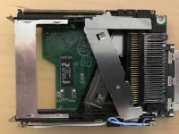
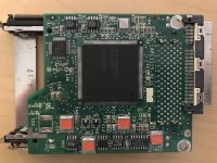
PowerBook 500 series PCMCIA module Rev C teardown

Trash80toHP_Mini

NIGHT STALKER
That cross-connection chart is what I've been working on from the other direction in the 1400. I was pleased to find the Blackbird PDS connector pinout documented. That should help a lot with tracing signals back to PBX from from the PC/IR Board interconnect in the 1400.


Charadis

Well-known member
If I ever get my hands on a Rev A or B (or both) card cage, first thing I'll do is disassemble it/them. I wasn't sure how serious of a project this could be, but I like where this momentum is going 


Charadis

Well-known member
Done, and removed the blockquote from around the content of the edited second post.
Mods are gods :)

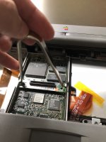
I finally got around to disassembling the 520. Recently got my IC extractor and I wanted to try it out anyways. Suffice to say, it did not disappoint. 
IMG_3562.JPG

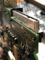
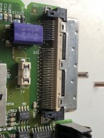
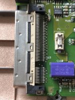
I'm going to say this is a draw. It appears there are three rows of pins. The first inner two, closest to the connector dock, seem to be through-hole/thruhole. The outer row, furthest from the connector, look to be surface-mounted. 
IMG_3569.JPG

From the other side of the board, we can see the inner two rows breach through the board. 
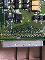
IMG_3572.JPG

I captured the battery connector SMC, which is north of the PDA port, and is also thru-hole. Note the similarities. 
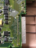
IMG_3574.JPG

Angled view to see the posts/pins

IMG_3582.JPG

Overhead view; it's hard to see all three rows of pins here. Someone is going to have a lot of fun unsoldering that! I will say, it will probably not be me. But..yeah :)

IMG_3583.JPG

Finally, I tried to capture all three rows from an angle. Note, behind the surface-mounted outer row 
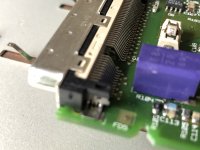
IMG_3584.JPG

Maybe a reflow would be best to remove this PDA connector? Then, I suppose you could furnish a breakout board, or pin converter, that would connect to a new adapter of your choice. That's just my $0.02


Trash80toHP_Mini

NIGHT STALKER
I hope you haven't buttoned it up yet. Out of curiosity, just how many of those 45(?) SMT connections are ground lines? I'm not at all familiar with the 040 PDS, but that's a lot of lines considering it's shy 16 of the data lines on the interface. Can't be an alternate ground line setup but it would be just too funny if one hella lot of those are the power & ground connections. Looks like only about four of the thru hole pins are connected to P&G planes.

Very curious.

edit: forgot to say thanks for the great pics!

 
Last edited by a moderator:

Charadis

Well-known member
Glad to help out.

Too late :-/  Honestly, I think the solder mask on top is a bit thick for me to discern any traces. However, it seems that the SMT row could be connected to vias through the board; you could see the zig-zag pattern of holes/vias preceding the SMT row where they connect. I counted the holes on the other side, also zig-zagged, above the thru-hole lines, and I think I see 40 vias?? Or 39...I don't know what one of them is. But I could be wrong on the count, but I can't tell what are ground/power traces on that front. 

Edit: Okay, I think I count 40 vias from the top. I've accounted for an additional 4 pins that lead to traces on top end of the board; the last pin on the short set (bottom) and the last three on the long set of pins (top most pins, closest to the battery connector side). 

 
Last edited by a moderator:

Bolle

Well-known member
Here we go with Rev B:

IMG_4416.JPG

IMG_4415.JPG

I can spot some differences right on the first sight.

Obvious one is the earlier revision of the controller IC being  343S0145 instead of a 343S0147 in the Rev C.

Some caps and resistors in different places as well. If I come across a cheap way to get my hands on one of those 343S0147s I can just go ahead and solder it onto my Rev B just to see what happens.

If someone with a Rev C is brave enough to desolder that Flashrom and read its contents that might help as well. Maybe there even is a way to read it from inside the OS.


Trash80toHP_Mini

NIGHT STALKER
Sweet, hoping you'll be doing the TREX controller swap out soon (ATM?) as I've got a shiny nickel laid on that process alone bringing you up to rev.3 features.

I'll put a shiny penny down on the FlashROM being added to rev.2 to fix something on rev.1 and not being a 2-3 rev upgrade concern. Anybody got rev.1 available for a comparison teardown?

If you're successful, or if anybody else wants to jump in, I'd love to see a performance comparison between the ethernet port implementation and a PCMCIA card in the same BlackBird.

LEM: myth or fact?

Apple eliminated the internal modem bay and the ethernet port found in the PowerBook 500 series that preceded the 190, forcing buyers to acquire these items separately. Because the PC Card uses a 16-bit bus, ethernet performance is roughly 25% slower than on the PowerBook 540.


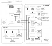
We now know the 16 bit bus limitation assumption above is incorrect:

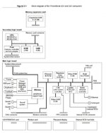
Blackbird-Block_Diagram.JPG

Let's put the pedal to the metal in both configurations to find out if there's an appreciable difference. If not we'll know that moving ethernet off the system board leaves the Card Cage half full (WiFi) and not half empty as is implied on LEM. If it is an appreciable difference, is the support of WiFi a good or bad tradeoff in terms of  feature set.

For the 190, it may be a tossup, but for the NuBus PPC series it's hands down WiFi for me. 5300ce/1400c kick the Blackbird (PPC onboard) up and down the block and twice around with their 800x600 LCDs IMO.
 

Edit: way cool, the pic preceding my LEM text quote transferred.

I'm also partial to the 190 as it's possible to upgrade it with a Duo TrackBall hack. Is the 500 series TrackPad as awful as I've read and did that tech improve in the 190/5300 generation?

 
Last edited by a moderator:

Trash80toHP_Mini

NIGHT STALKER
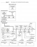
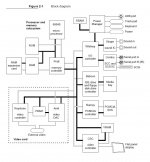
Bolle just set off the curiosity. Took a look at the DevNotes:

Looks like we may have another PCMCIA controller to try if TREX from 5300/1400 doesn't work out:

PB190-Block_Diagram.JPG

Has anyone got a 190 board handy to take a pic of Barney? I'm guessing these are probably all Apple tweaks/revisions of the same off the shelf PCMCIA controller series. I don't recall using a WiFi card in my 190, can anyone confirm compatibility?

edit: 5300xx Block Diagram

PB5300xx-Block_Diagram.JPG

So we've got Pratt & Whitney memory controllers in the mix with Barney and T-REX. Gotta love Apple's naming conventions.

 
Last edited by a moderator:

Trash80toHP_Mini

NIGHT STALKER
What's one more project box? Luckily it was only the bottom half of the 190 awaiting a "c" upgrade.

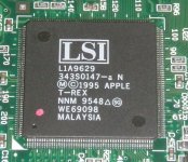
Still need a picture of Barney, now we've got another oddity in the mix. My 190 has T-REX on board!  :shocked:

PB190-T_REX_not_Barney.JPG

edit: Just realized this could be a good omen. T-REX is backward compatible with Barney, so it might also work in the Rev.2 Card Cage for the Blackbirds? If not, then Barney?

T-Rex availability in the 1400 "DaughterCage" is much greater. Sound 1400 lid plastics are hard to come by, so cannibalization isn't as much of an issue. "Borrowing" that cage from a good 1400 board is easily reversible, it can wait for a bad board cage donor to show up. [;)]

 
Last edited by a moderator:

Charadis

Well-known member
Here we go with Rev B:

I can spot some differences right on the first sight.

Obvious one is the earlier revision of the controller IC being  343S0145 instead of a 343S0147 in the Rev C.

Some caps and resistors in different places as well. If I come across a cheap way to get my hands on one of those 343S0147s I can just go ahead and solder it onto my Rev B just to see what happens.

If someone with a Rev C is brave enough to desolder that Flashrom and read its contents that might help as well. Maybe there even is a way to read it from inside the OS.
Whoa, I didn't realize you posted this, or that this thread had any movement going - I've been working on some other project lately. Thanks for posting the Rev B board! I thought the two would be much more different; it still doesn't seem like a simple chip swap. If you have software that can allow me to read the Flashrom, I can try that as soon as I am back in town.

Would like to save desoldering as a last resort (better if I can obtain another Rev C and use the other in the name of science..nondestructively, of course, but invasively if necessary)

 
Last edited by a moderator:

Charadis

Well-known member
What's one more project box? Luckily it was only the bottom half of the 190 awaiting a "c" upgrade.

Still need a picture of Barney, now we've got another oddity in the mix. My 190 has T-REX on board!  :shocked:

edit: Just realized this could be a good om


Here's a PB 1400 card cage if you're looking for one! 

https://www.ebay.com/itm/Macintosh-Powerbook-1400CS-1400cs-166-M3571-PCMCIA-Assembly-With-Infrared-Board/312115560867?_trkparms=aid%3D222007%26algo%3DSIC.MBE%26ao%3D2%26asc%3D50543%26meid%3Db00b064448174309bcdb82315496ef2a%26pid%3D100011%26rk%3D1%26rkt%3D1%26sd%3D312091104242%26itm%3D312115560867&_trksid=p2047675.c100011.m1850

 
Last edited by a moderator:

Franklinstein

Well-known member
A little bit of info to add:

I recently acquired both a Rev. B and a complete boxed Rev. C expansion module. When attempting to install the Rev. C’s included PC Card Software 2.0 with the Rev. B card, the installer generates an error saying ‘this software cannot be used with this module; it must first be upgraded.’ This suggests that there was once a way to upgrade Rev. B modules, probably by reprogramming that Flash chip, but I have seen no references to any upgrade procedures. Maybe it was an Apple Service-exclusive procedure not available to the end users. 


techknight

Well-known member
Depends on how you comprehend the term "Upgraded" 

Because Upgraded could mean something as simple as just replacing the PCMCIA adapter with the upgraded newer version. It could go either way. There is a flash ROM on the PCB so anything is possible, but if the control IC itself is different, its hard to code around that. 

 
Last edited by a moderator:

Franklinstein

Well-known member
Further reading suggests that in fact the only way to upgrade a Rev. A or B module is to replace the board (and the card cage since it's soldered together) with a Rev. C board assembly. Since the price difference between upgrading a Rev. A or B module and just buying a new Rev. C module is likely to be minor, I don't think I would have gone for the upgrade; I'd have bought a new Rev. C mod and resold the earlier one. 

The part number for the controller in my Rev. B module is 343S0145 while that used by the Rev. C module and every 190, 5300, and 1400 is 343S0147, so 147 appears to be the final iteration of the PCMCIA controller chip for the pre-PCI PowerBooks. While the 145 and 147 controller chips are very likely to be pin-compatible I don't know if there's something on the accompanying Flash chip that would also need to change, and if it did I have no idea how you'd program it in place. If there weren't so many fine-pitched pins on the controller chip and the older PCMCIA Modules were plentiful enough for experimental surgery, I'd give it a go; I have plenty of mostly useless 5300 and 190 logic boards whose controller chips could be liberated for the cause but only one PCMCIA Rev. B module and I'd prefer not to destroy it.


Paralel

Well-known member
Given the developers note, could a Cardbus compatible card cage be designed?

It seems like it could. I think the only reason they implemented the 16-bit PCMCIA standard is that the PC Card 3.0 standard that introduced CardBus wasn't created until the blackbird was already out for a year. The PDS connector allows for 32-bit bidirectional communication, it seems like that would support cardbus. The power available is 5V 600 mA + a secondary power tap that is 8-16 volts 300 mA, which also seems like more than enough. They had to use TREX for the protocol translation back then, but we have substantially better development board and chips now that could handle the translation between the MC68030 that the PDS connector speaks and whatever it needs to communicate with.

Cardbus would allow for just about anything anyone could want.

I have no doubt it would be a big seller. Everyone that has a blackbird would want one.
 

jeremywork

Well-known member
The PDS connector allows for 32-bit bidirectional communication
Normally PDS does this, though the PDS in the Blackbird is located behind the 16-bit 030 bus (adapted from 32-bit 040 bus at the CPU daughterboard interface.) Only the CPU, ROM and memory have full-speed 32-bit communication.

Perhaps it would still be possible to add a compatibility layer for slow cardbus support, but that's well beyond my depth of research for now :)

Edit:
Re-reading the thread, is the "16-bit system bus" indication on this document erroneous?
I'll make an effort to do some speed testing with rev C, (rev B?), and onboard AAUI based ethernet interfaces to see what difference there is.

Blackbird-Block_Diagram.thumb.JPG.88d6b63d1942e1583f37c07213dd110f.jpeg
 
Last edited:

Fizzbinn

Well-known member
The PDS connector allows for 32-bit bidirectional communication, it seems like that would support cardbus.

Re-reading the thread, is the "16-bit system bus" indication on this document erroneous?

I don't think so, in addition to the diagram label the PB 500 series Hardware Developer Note says the PDS data bus is 16-bit on page 46:
"DATA[31–16] Bidirectional 16-bit system data bus."

I don't think any of the devices on the I/O bus require/could make use of a 32-bit data bus? For example, pulling the PB 160/180 Hardware Developer notes where they call out more detail on data and address bus lines going to the devices the "Combo" uses just 8 data bus lines.

Edit: Looking at other Dev notes the "Sonic" Ethernet controller does use a 32-bit data bus. (Quadra 800, Duo Dock II). However it is apparently compatible with 32- and 16-bit systems according to its docs. So I guess the diagram could be wrong and all 32 bits of the 030 data bus are on the I/O side just not used by most of the devices and not included in the PDS connector.
 
Last edited:
Top