-
 Hello Guest! We're hosting a challenge to welcome vintage Intel macs to the MLA during the month of July! See this thread for more information.
 -
We've made some quality of life improvements to the Trading Post. More info here.
You are using an out of date browser. It may not display this or other websites correctly.
You should upgrade or use an alternative browser.
You should upgrade or use an alternative browser.
Overclock LC475/P475/Q605 without soldering or spicy-o-clock
- Thread starter Mustermann
- Start date


It doesn't seem to matter. Tried yet another board that has a 343S0161 and it works just as expected.Very interesting, can anyone confirm the "343S0161" vs "343S1135" thing?
Not sure what's wrong with the very first board I used for testing this and why it wouldn't talk to the clock chip.
Meanwhile I added a few extra values to the code to reach up to 50MHz... 45MHz seems stable, anything faster crashes once you try to do anything after setting the speed. That's with 50ns RAM but only 70ns VRAM as I haven't anything faster at hand. SCSI clock selection resistor is set for bus clock/2 so the SCSI chip isn't overclocked.
Last edited:
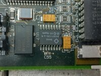
This side is telling:Nevermind, works on a different logicboard. What's interesting, the non-working board has a "343S0161" installed for the clock chip, the working one has a "343S1135" - what's on your board @Mustermann?
All my boards have a MC88916 swapped in place, no problem to go up to 42MHz... we need faster settings now
| 343S0161 | Gazelle | Video clock generator, LC 475/575, Quadra 605 |
Driver:Mac 68K:Tech Info:ASICs - MAMEDEV Wiki
My LC475 has a 343S1135
Is leg 9 of U17 of non cooperative device lifted and pulled to 5V by a resistor to achieve 40Mhz?
Attachments
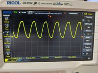
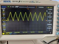
Checked with , Checked with Norton Sysinfo(Post #1), clockometer(Post#11) and Osziloscope at R96(Picture attached, frequency can be found at the bottom line of screen)For reproducibility: how are you validating that you're getting the frequency you think you're getting?
Attachments
All my tests until now were operating with 1152*870*8bit @75Hz using 60ns VRAMDo you have any issues with outputting any resolution aside from 640x480 when changing the clock? Maybe stupid question, gotta ask though.
Right now I tested 640*480, 800*600, 1024*768, and 1152*870 @38Mhz with 80ns VRAM
and 1152*870 @38Mhz with 60ns VRAM
All of them work but switching resolution @38Mhz stopped with black screen.
When first switched back to 25Mhz resolution change was possible.
I am not sure if ROM is setting VRAM timing in FrameBufferConfiguration
@Bolle If you have a LC475 with 33Mhz resistor mod at hand, may you post the output of my program prior first speed change.
If 4 most significant bits are 0000 when starting with 33Mhz ROM does not set these bits as proposed in MEMCjr datasheet (0010).
Starting with the good news: Will work.I haven’t tried this yet @Mustermann but what would happen on a resistor swapped board where it is set to 33mhz on the board?
But it is not only the "loading at startup" topic.
When starting, Gazelle will read resistors and chose 33Mhz dataset from internal table (if resistors are changed for 33Mhz).
When changing to to any value using the "setlong" function in my code, the 33Mhz entry will be replaced by the variable entry (e.g.38Mhz).
I am not sure if a reboot will reset this or if a power-down cycle is needed.
Starting with the good news: Will work.
But it is not only the "loading at startup" topic.
When starting, Gazelle will read resistors and chose 33Mhz dataset from internal table (if resistors are changed for 33Mhz).
When changing to to any value using the "setlong" function in my code, the 33Mhz entry will be replaced by the variable entry (e.g.38Mhz).
I am not sure if a reboot will reset this or if a power-down cycle is needed.
I'm going to try my 475 when I get home this afternoon, unless someone else wants to try. Hopefully my rasPi ethernet bridge still works.
Just to let you know, how to calculate parameters for "setlong" function.Meanwhile I added a few extra values to the code to reach up to 50MHz...
case 29:
setregistermin(0);
setregistermax(3);
setlong(13,7,2);
setregistermin(1);
setregistermax(2);
break;
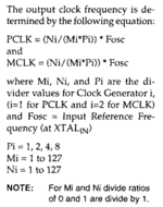
setlong expect 3 parameters corresponding to Ni, Mi, and Pi in the calculation from the datasheet (attached).
First choose desired Clock-speed (29Mhz)
Than add 0,1 as 29,05Mhz is nicer that 28,95Mhz (29,1Mhz)
Next divide by 2 as MC88920/16 will double the frequency later on(14,55Mhz)
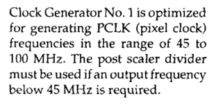
Chose divider P from 1,2,4,8 in that way that 14,55*P is smaller than 100Mhz and bigger than 45Mhz
For 20-25Mhz CPU clock 8 will work, for 25-50Mhz 4 will work, above use 2,
Multiplier 1 is coded as 0 in last parameter
Multiplier 2 is coded as 1 in last parameter
Multiplier 4 is coded as 2 in last parameter
Multiplier 8 is coded as 3 in last parameter
So 14,55Mhz*4=58,2Mhz. Last parameter = 2
Next divide crystal frequency (31,3344Mhz) by the frequency calculated (58,2Mhz)
Results 0.538391753
Ask your spreadsheet calculation to format that as a two-digit fraction:
7/13
Enter last number (counter)(13) as first parameter Ni and first number (denominator)(7) as second parameter Mi.
I am not sure if it is really named counter and denominator.
Attachments
This side is telling:
343S0161 Gazelle Video clock generator, LC 475/575, Quadra 605 No information about 343S1135 on that side.Driver:Mac 68K:Tech Info:ASICs - MAMEDEV Wiki
wiki.mamedev.org
| 343S1060 | Omega | PLL clock synthesizer, very similar to Gazelle and Sierra Semiconductor SC11412. LC III/III+, LC 520, LC 550 |
Omega does not seem to be as similar to the SC11412 as Gazelle.
Omega might have 28 pins (based on LCIII schematics).
Is there a datasheet for Omega?
Omega might have 28 pins (based on LCIII schematics).
Is there a datasheet for Omega?
There is, but I typed all this header comment up so it's not necessary ;-)

 github.com
mame/src/mame/apple/omega.cpp at master · mamedev/mame
MAME. Contribute to mamedev/mame development by creating an account on GitHub.
github.com
Side note:Do you have any issues with outputting any resolution aside from 640x480 when changing the clock? Maybe stupid question, gotta ask though.
This well-known page
Q605overclock40mhz.pdf
 drive.google.com
From this thread we know, that pin 9 is used as DATA line to transfer data from MEMCjr to Gazelle.
Gazelle is also generating Dot_Clk for Antelope Grafik Chip.
If lifted pin 9 and pull to 5V the System is no longer able to change Dot_Clk frequency.
Gazelle will stay at the clock frequency that is internally defined for power-up.
I do not wonder that there are resolution issues with other than minimum resolution when lifting pin 9.
Fortunately this is no longer needed.
Any C Compiler should work.
Any recommendations? Assuming this has to be compiled into a classic Mac app?Any C Compiler should work.
Ooo, someone could put a nice GUI front end on it, ala Daystars QuadControl or something similar.Any recommendations? Assuming this has to be compiled into a classic Mac app?
Sweet find. Here's a quick and dirty extension to set 40mhz based on the code posted by @Mustermann. It loads as early as possible during the boot process to get running fast ASAP. Seems to work correctly: Clockometer reports 40mhz & corresponding speed improvement in Speedometer.
Also includes Symantec C project to compile. It's all hardcoded, if you want to try something else you'll need to pick different parameters and stick them in there.
Also includes Symantec C project to compile. It's all hardcoded, if you want to try something else you'll need to pick different parameters and stick them in there.
Attachments
Similar threads
- Replies
- 20
- Views
- 5K
- Replies
- 10
- Views
- 2K
- Replies
- 9
- Views
- 5K