• Updated 2023-07-12: Hello, Guest! Welcome back, and be sure to check out this follow-up post about our outage a week or so ago.

Serious proposal: accelerator and peripheral expansion system

ZaneKaminski

Well-known member
Version 2 of the Mac SE accelerator schematic is done. I've attached it to this post. SE/30 will be done tomorrow or Friday.

Maccelerator-SE.pdf

This version is a bit transitional, in that it uses the Variscite Dart 410 module, when I actually plan to use the Intrinsyc Open-Q 410. I just can't see the pinout of the Open-Q 410 until I receive mine. Only customers with a serial number can see that info. Ugh.


Attachments

  • Maccelerator-SE.pdf
    1.8 MB · Views: 175
Last edited by a moderator:

Trash80toHP_Mini

NIGHT STALKER
Thank you for the encouraging words, sstaylor.

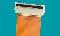
The coolest feature I've added in this version is certainly the display sub-board connector. I've added a low-profile, shielded, 30-pin board-to-board connector that breaks out the MIPI-DSI display interface. Looks like this:

/monthly_11_2016/post-6543-0-93911400-1479832475.jpg">View attachment 10671
Very nice and I'd like to ditto sstaylor''s encouragement.

Not to derail things, but linkage to the source of those cables and the matching board connectors would be greatly appreciated. They'd make a couple or three of my own development projects a lot easier than originally planned! :approve:

 
Last edited by a moderator:

ZaneKaminski

Well-known member
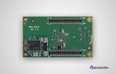
The picture I posted wasn't of the exact series I'm using. What I plan to use is from the Hirose DF40 series. They're also used in the Snapdragon modules I'm looking at.

DART-SD410_BOTTOM.jpg

Here's a link to the series on Digi-Key:

http://www.digikey.com/product-search/en/connectors-interconnects/rectangular-board-to-board-connectors-arrays-edge-type-mezzanine/1442154?FV=ffec4097%2Cfff40016%2Cfff8016a&mnonly=0&newproducts=0&ColumnSort=0&page=1&stock=0&pbfree=0&rohs=0&quantity=0&ptm=0&fid=0&pageSize=500

There are shielded and unshielded models available. The shielded ones are better for high-speed signal applications, but they are available in fewer sizes. If your signals are in the tens of MHz or less it should be fine to use an unshielded one as long as you sprinkle around enough ground reference pins.

 
Last edited by a moderator:

Trash80toHP_Mini

NIGHT STALKER
Thanks much, Zane, very helpful. Not to be too lazy, but if you have a chance, a direct link to the appropriate cables page would be greatly appreciated. [:)] ]'>

LOVE your project, way over my head, but fascinating all the same. One suggestion: you might look into building your card for the IIci Cache Slot interface. There are plenty of adapters available for reverse engineering for the PowerCache accelerators in the 68k Mac lineup, including a fairly simple one for the SE/30 and IIsi.

Cloning the Daystar PDS Adapter for the SE/30 - Take 2

Targeting the IIci cache slot interface would open up your user base to all who already have PowerCache accelerators on hand for all their machines, including PDS slotless Macs like the Mac II, IIx and IIcx.

If I can find a link to the PowerCache Adapter tree graphic or find it on disk, I'll post that here if you'd like.


ZaneKaminski

Well-known member
I think it should be very straightforward to port the schematic for SE/30 to the IIci's cache slot. It has basically the same signals as the SE/30 PDS. Of course, someone else has to design the board... I just don't have time to do it, and nor do I have a IIci.

For the rest of the Mac II series and any other NuBus-equipped Macs, the design of the bus interface FPGAs has to be redone to talk to the Mac's hardware over NuBus, but everything above the bus interface (Snapdragon, emulator, Linux system, etc.) should work without modification, as long as the FPGA-Snapdragon interface remains the same.


ZaneKaminski

Well-known member
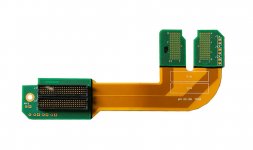
Oh, cables. You mean the flat-flex kind? I dunno much about those.

Premo-Flex_FFC_Etched_Polyimide_Jumpers.jpg

I was just going to mount the connector onto the accelerator board, and then the display sub-board would mate to it and be secured with a few screws. No cables, just the connector sockets mating the boards directly.

My understanding with the flat-flex cables is that you get the cables and then solder on the connector. I think the cables can be custom-made, similar to how a PCB is designed and produced.

There are also rigid-flex PCBs, where the internal layers are basically a flat-flex cable, and you can decide what portions are rigid and which are the cable.

15_defibrillator-circuit_rigid-flex.jpg

These are really expensive though, totally out of range for hobby stuff.


Trash80toHP_Mini

NIGHT STALKER
Thanks for the info, I'll have to look into flex cable possibilities.

I think it should be very straightforward to port the schematic for SE/30 to the IIci's cache slot. It has basically the same signals as the SE/30 PDS. Of course, someone else has to design the board... I just don't have time to do it, and nor do I have a IIci..
The PowerCache adapter for the LCIII is completely passive, just resistors and caps on the board. If you've got an LCIII, I've got a couple of those boards on hand, so if you're in the US and you'd like one, it's yours for the asking. That combo adds up to a IIci.


ZaneKaminski

Well-known member
Thanks, but no thanks. Like I said, I don't have time to do a board for IIci, but anyone is welcome to try to adapt what I have once I've made more progress. It's also a little early in the project for me to be accepting hardware donations lol, maybe once I have some kind of proof-of-concept working. That's months away though.

First, I will do the Mac SE board, and then move on to the SE/30. SE is easier since the 68000, compared to the 68030, has fewer instructions, a smaller address space, and no MMU. The MMU emulation especially will be complicated.

The 68000 has 24 address bits plus 3 function code bits, so that's a 27-bit address space at maximum, or 128 Mbytes. Dividing that into regions as fine as 256 bytes, that's only 512k entries in the address space table. So the overall address space table size will be small, and the immediacy of checking a region in the address space table lends to good performance for memory accesses.

A 68030-compatible emulator for SE/30 has to implement the 68030 MMU, which has this tree structure that it traverses to find out how to translate a given address. Not that hard to implement or anything, but it may impose an interesting performance penalty... cached translations of the M68k code may have to be purged from memory when the translation tree is changed. Not sure about this part yet. Let me tackle Mac SE and MC68000 first.

 
Last edited by a moderator:

Trash80toHP_Mini

NIGHT STALKER
Gotcha! One other thing though, was wondering if you knew that when you're designing for the SE, you're also designing for the Plus and the Classic. If you have room on your board to parallel your SE EuroDin PDS connector with thruholes for a 68000 socket as shown, you're also tripling your user base. Now as then, in terms of development it's all about economies of scale.

micromac030160502.jpg.ade8f8c833c2192cfbb039187a3185d8.jpg


Since your board's profile will undoubtedly be far lower than that of this MicroMac accelerator, the CPU/PDS interface adaptation could probably be done with a directly soldered header interconnected daughtercard underneath your PDS card.. It'll be interesting to hear from techknight if something similar might be possible for the Portable's CPU interface.

One wonders if the marvels of rapid prototyping might pave the way for a reproduction of the Killy Klip interconnect hardware for this and many other 68000 board installations?

 
Last edited by a moderator:

asaggynoodle

Well-known member
So I'm curious as to what kind of Time Table we're talking about here for a first revision physical prototype?

Also, are you planning for the board house to do all/some (QFP/BGA's) of the component level work, or are you planning on doing that yourself/selling as a kit?

 
Last edited by a moderator:

ZaneKaminski

Well-known member
No idea. I have decided to put SE/30 on hold for now as well. The SE design is too young and unstable to turn it into a "master schematic" and fork that for each supported machine. That's what I was trying to do in the past few days, but when the schematic is changing so fast, that's a pain.


The only commitment I can make relating to the schedule is that I'll spend a lot of my spare time on the project haha. This is, for me, a learning experience, so I may make a ton of mistakes and it may take a while. I think that the only way these types of projects are completed are by someone who is in it more for the learning than to have the final product, y'know the super Mac or whatever.
 
About the boards, I'll definitely release all of the source files eventually, so you could go yourself to OSHPark or some other board fab and purchase the board yourself, solder the components on, program the FPGAs over JTAG (current design has a system controller that can bit-bang JTAG to update the FPGA software, but I don't plan on implementing that, so you will need an external programmer), and put the Snapdragon in the socket, and use a microSD card with the software I'll provide to boot the Snapdragon up.
 
Now, for at least SE, maybe more models, I will probably sell fully assembled units myself. I have explicitly avoided BGA parts, so I will be able to reflow the boards myself or hire a friend skilled in that stuff to do it. In order to do this, however, I will have to have a Kickstarter or something to raise the funds required to build the boards. If more than 25 or 40 boards are in demand, I will outsource production to China, since that's around when it becomes affordable.


Gotcha! One other thing though, was wondering if you knew that when you're designing for the SE, you're also designing for the Plus and the Classic. If you have room on your board to parallel your SE EuroDin PDS connector with thruholes for a 68000 socket as shown, you're also tripling your user base. Now as then, in terms of development it's all about economies of scale.
 
Since your board's profile will undoubtedly be far lower than that of this MicroMac accelerator, the CPU/PDS interface adaptation could probably be done with a directly soldered header interconnected daughtercard underneath your PDS card.. It'll be interesting to hear from techknight if something similar might be possible for the Portable's CPU interface.
 
One wonders if the marvels of rapid prototyping might pave the way for a reproduction of the Killy Klip interconnect hardware for this and many other 68000 board installations?
It's tempting, but there are a few notable electrical differences.
 
Firstly, the SE has this scheme where the ~8 MHz clock is like 90 degrees out of phase of the ~16 MHz clock from which it is generated. I don't think the 128k - Plus do that.
 
If we replaced the 68000, we would also have to generate ECLK. Clock routing is a pain, though the E clock is only 783 kHz, so that's in no way fast, but in general, clock routing is a pain and doing it improperly is a common source of problems. In the last schematic I posted, I had the clocks connected to the system controller, thinking that it might be useful to measure their frequency or run synchronous to them or something. I have since removed that feature. Maybe in the SE/30 design, the system controller will have to take in the 16 MHz clock and make 32 MHz from it, from which the FPGA control logic will run, but no need to complicate things for the SE.
 
It is tempting to try and copy the shape of that MicroMac card, though... hmm. The mechanical engineering part of it, making sure it fits properly, is really not one of my strong areas. Also mine may be thicker than the traditional accelerators. The snapdragon module is a few millimeters tall, just like the 68030 on that board you posted.
 
Maybe once I have it all together for SE, I can try adding those extra pins, but I'm already wrestling with a lot of complexity as it is. The cost of the boards is also not going to be that much if I can manage to buy 25 or so boards for each supported machine. See my reply to asaggynoodle above about how I plan to build them.

 
Last edited by a moderator:

ZaneKaminski

Well-known member
Actually, I change my mind. Supporting the 128k - Plus is more important than supporting the SE/30, right? So maybe I should drop SE/30 entirely and support all the 68000 compacts. That's easier than supporting 68000 and 68030.

 
Last edited by a moderator:

ZaneKaminski

Well-known member
Since I'm halting work on the SE/30 schematic for now. I'm moving on to the board for the SE. Maybe it will pick up 128k-Plus and/or Classic compatibility eventually, but I am counting more on just doing another board for those. More boards means more work, but also routing a board with a bunch of differently shaped footprints (DIP 68000, PGA 68000, and SE PDS) is harder too.


Trash80toHP_Mini

NIGHT STALKER
Actually, I change my mind. Supporting the 128k - Plus is more important than supporting the SE/30, right? So maybe I should drop SE/30 entirely and support all the 68000 compacts. That's easier than supporting 68000 and 68030.
Probably not on your comment re: importance (more on that later) of support. The SE/30 gang is probably the most invested segment of the 68k community in terms of interest and CERTAINLY in terms of spending in order to amp the little beast up.

Dunno if you can use the same SE/Plus/Classic setup for the 128k/512k/512ke. I had a board that worked on 128k through 512ke back in the day and now I've got this one for SE/Plus/Classic, but I don't know if the two fairly distinct generations are compatible or not. IMO, anything useful for the earlier models would need to have the added complication of RAM expansion on board to be of much use for anything practical. Such was the case with the NewLife(?) board for my 512k. Playing with those early models seems to me to be a joyous celebration of the impractical. So the generational compatibility issue would be moot from my point of view.

The beauty of work based on the MicroMac model and board layout yields three machine compatibility (at least) without doing different boards. Work based upon the IIci Cache Slot model yields compatibility with dozens of 68030 based Macintosh models using original DayStar units or redesigned versions of their PowerCache adapters with a single board design.

You'd be doing one board with either/or connector installation for a minimum of three 68000 based Macs and a single board for nearly the entire 68030 based family of the Macintosh.

Keeping those two board designs within unofficial (68000) design restraints and Apple's Spec for the IIci Cache Slot seems he obvious way to go to me. The notion of doing different boards for specific models as opposed to just two boards for two entire families of models gives me the heebie-jeebies.

But that's just me, so I'll be quiet now. :I


Trash80toHP_Mini

NIGHT STALKER
I know I said I'd be quiet, but a couple of things jumped out at me.

.  .  .  but there are a few notable electrical differences.

Firstly, the SE has this scheme where the ~8 MHz clock is like 90 degrees out of phase of the ~16 MHz clock from which it is generated. I don't think the 128k - Plus do that.

If we replaced the 68000  .  .  .
On the former, the MicroMac board would seem to point to the Plus handling things like the later models, that could be why I've seen the division of generations as I stated above.

In no case are we replacing the 68000, the SE has its EuroDin PDS connector and the other clips to all of the legs of the existing 68000  .  .  .  how's that for a direct slot? So much for the Steve's slotless design edict! HEH!  [:D] ]'> 

OK, now I will be quiet  .  .  . ::)


ZaneKaminski

Well-known member
No lol please argue with me. I want my effort to be best spent.

Some new factors are influencing my decision about it, and I think I oughta add compatibility with as many 68000 compacts as I can.

I realized about the SE/30, there's no point to do the schematic now, since the 68030 emulator won't be done until after the 68000 functionality is stable. 68000 emulation is also a lot easier than 68030. Therefore, maybe I oughta direct my effort I was gonna spend on an SE/30 board on making a single board compatible with many 68000 models. If the wider compatibility gets the project more attention, then someone might come along and do the SE/30, IIci, or NuBus board. At that point, I could add the 68030 opcodes and MMU stuff to the emulator.

Also, I forgot that SE and SE/30 PDS cards are different shapes and sizes. SE/30 cards stand up vertically and can be much more compact than SE cards, which must be almost as wide as the Macintosh's digital board in order to sit on some supports. So if the card must me that large, it would be better to support more models since it will have to be produced in larger quantities to achieve the same unit cost.

Though your card you posted was not so wide. It was seemingly supported in other locations. I would like a little more routing room than is provided on that card, though.

Plus and SE are the most popular compacts, right? How common are Classics (especially among buyers of a $150 accelerator)?

And tell me about this clip for the DIP chips. Can you buy one that fits the 68000? I couldn't find one online, but I didn't look too hard.

About the generations of Mac, I think the Plus is much more similar to the 128k than SE. There must be some modification to the RAM address decoding stuff to support memory expansion, but I think it's basically the same "Burrell logic" used in the original. The only difference may be a few new traces or slightly different programming of the PALs. See here: http://www.folklore.org/StoryView.py?project=Macintosh&story=Macintosh_Prototypes.txt&sortOrder=Sort+by+Date&topic=Hardware+Designand http://www.folklore.org/StoryView.py?project=Macintosh&story=Five_Different_Macs.txt&sortOrder=Sort+by+Date&topic=Hardware+Design

Also this one, "Diagnostic Port," is funny: http://www.folklore.org/StoryView.py?project=Macintosh&story=Diagnostic_Port.txt&sortOrder=Sort+by+Date&topic=Hardware+Design

The SE has the "Bob Bailey Unit," which replaces the Burrell logic. When feeding the video, it fetches two words in series from the RAM, so video accesses are half as frequent during the active portion of display refresh. The BBU also generates the PMCYC signal that informs the PDS card when a video access to memory is occurring and also allows the PDS card to synchronize itself to the Mac's memory cycle timing.

I dunno what the Classic has. It must be similar to the BBU, but withot the expansion card stuff.

 
Last edited by a moderator:

ZaneKaminski

Well-known member
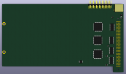
Screwing around with placement of components... the Mac SE PDS board shape specified in Designing Cards and Drivers for the Macintosh Family is huge.

Screen Shot 2016-11-26 at 3.38.18 AM.png

It's gotta be wide to be held up by the screws on the left, and it's also gotta be tall to have its connectors in the right area.

Once I get the Intrinsyc 410 module, I can actually do the board. Right now I'm just playing.

I think I'm going to aim for compatibility with SE and Plus, provided I can get the DIP clip thing.

So huge though, ugh. Trash, how does your accelerator support itself when in the SE? What about when in the Plus? I'd like to copy or at least be inspired by the locations of its stands.

 
Last edited by a moderator:

Trash80toHP_Mini

NIGHT STALKER
The MicroMac board has no, and doesn't really need any supports. The Killy Klip provides plenty of support in the Plus and by extension, I assume the case would be the same in the Classic.

The Killy Klip is very rare beast in this day and age. I'll post a pic of the one in my DrexelMac. I think it's a good candidate for rapid prototype printing, assuming a jig could be made to hold the flexible pins or they could be inserted at some point during a break in the printing process.

Some 68000 packages were incompatible with the Killy Klip as was the case with the CPU on the 128k board I picked up from the long defunct Shreve Systems for my CatMac/Hackintosh. The alternate method of mounting the NewLife board (or any other accelerator/expansion card) was to use a 68000 socket as a jig for the process of soldering rows of header pins directly to the legs of the 68000 to mate with the 68000 socket on the bottom of Compact Mac expansion cards.

Such modification was no big deal back when expansion was an absolute necessity in meeting Desktop Publishing requirements in the early days of the Mac. Today, folks seem to prefer reversible means of expansion. Personally, I consider the header modification of Compact boards to be more historically correct. The Killy Klip was invented later on as an easier/alternate method for less technically oriented users to execute expansion via the "original 68000 PDS" expansion slot.

This ingenious "PDS" hack of the 68000 sitting right out there in the open on the 128k board lends much humor regarding the irony in Folklore's revelation of the "Diagnostic Port" caper. :D

A for support for the SE implementation (possibly an unimplemented 68000 version of my MicroMac card) would likely have been nylon standoffs mounted in the convenient holes in the PCB. That was the standard method of support for cards designed outsized for Apples' specifications for the LC PDS  .  .  .

to be continued  .  .  .

 
Last edited by a moderator:

ZaneKaminski

Well-known member
I'm liking the idea of designing the DIP-64 Killy Klip. Designing the body and having it 3D printed is the easy part. The hard part is finding the right contacts. They've gotta be fat and kind of rolled or V-shaped where they touch the 68000's legs, but long, straight, and thick enough on the other side to be soldered into the board.

I've got a bit of experience with solid modeling. Like I said, mech. eng. is not my field but I'm sure I can come up with something good. Once I find a contact that suits me, I'll do up a model and have it printed.

I think the contacts can be friction-fitted in the plastic body of the Killy Klip, as long as the straight side of the contact (which is to be soldered to the accelerator) is strong enough to be forced through an opening slightly too small. Soldering the pin to the accelerator board above would secure it permanently.

 
Last edited by a moderator:
Top