• Updated 2023-07-12: Hello, Guest! Welcome back, and be sure to check out this follow-up post about our outage a week or so ago.

SE/30: Micron Xceed Video Card, DB-15 to VGA

JDW

Well-known member
Try adding some solder only on the back side... I am still having problems on some logicboards even though it’s a tight fit with the added thickness.
So adding solder to only the back side will help but not entirely solve the problem.  OK.  Thank you for the first-hand experience.  It's a crying shame there's no perfect fix because the ROM-inator II MEGA is superb otherwise.


JDW

Well-known member
@Bolle I am looking at my SE/30 now.  Are you sure that adding solder to the BACK side of the ROM (not the chip-side, but the BACK side) is best?  I would think the opposite would be true.  The pins pressing on the back look locked in place whereas the pins on the chip-side of the ROM seem to move a little.  There's no way I can apply fresh solder to all the pads evenly (some solder will be raised up very slightly higher on some pads than others), I would think doing that on the chip-side would be best, since the motherboard pins could probably accommodate that better.  Again, please let me know your thoughts.  I'm a bit afraid to do anything for feature of messing up my ROM-inator.

Well, I tested with my Xceed MacroColor 30HR (the one with VRAM problems).  My VGA display did not work at all with it.  Not sure if that is related to the VRAM problem (I doubt it), or related to my DIP-less adapter.  Since I don't have an adapter with DIP switches, I cannot know for sure.  And silly Amazon sellers in the USA refuse to ship to me in Japan.  So if any of you have a spare DB-15 to VGA adapter with DIP switches you are willing to part with, please send me a Message!


JDW

Well-known member
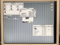
Here's a photo showing how 1024x768 looks on my VGA display at 16 colors (which are the max colors for the Xceed Color 30HR), and note how it is shifted to the left and up too much on the display:

1024x768.jpg

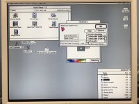
And here's a photo at 832x624, also with 16 colors and this time shifted up and to the right too much:

832x624.jpg

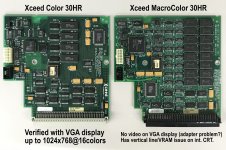
And here's a side-by-side of my two Xceed video cards:

XceedCards.jpg

Here is the Xceed Video Card Comparison Chart.

I'd really like to test my MacroColor 30HR with the VGA display, but again, I need an adapter with DIP switches to do that.  Any generous souls out there with a spare one, please Message me.

 
Last edited by a moderator:

NJRoadfan

Well-known member
If the Xceed card only has pin 3 and is following the standard DA-15 video pinout, its only outputting composite sync any maybe sync-on-green. VGA monitors only support separate horizontal and vertical sync with a small subset also supporting composite or SoG. Many of the switched adapters have a built in sync separator to convert the composite sync or sync-on-green to separate H+V sync. You can build a relatively simple circuit using a LMH1980 chip too.


trag

Well-known member
Problem is that most manufacturers only offer boards with 1.2mm or 1.6mm thickness. We would need 1.4mm for the ROM socket.

I tried 1.6mm and it’s way too thick and damages the contacts in the socket if you’re not super careful.


Is it 1.4mm?  I ask, because I thought that the old ROM SIMMs and 30 pin SIMMs are .050".    While newer stuff is pretty standard at .063".

Ah, did a little googling and the drawings I found, though I'm not sure how standard they are, indicate that the thickness should be .047" to .055", which is 1.19mm to 1.4mm.   

So 1.2mm is near the extreme thin side of the specification and 1.4 is near the extreme large end of the specification.   Larger is likely to result in a snugger fit...

Ah, found this drawing from AMP, at DigiKey for the 822019-2 64 pin socket (822019 drawing is actually for several different pin counts, but -2 is 64 pins).

According to this drawing, the SIMM should, indeed be (.047") 1.19mm to (.054") 1.37mm with .050" (1.27 mm) as the nominal thickness.

View attachment 822019.pdf

 
Last edited by a moderator:

JDW

Well-known member
According to this drawing, the SIMM should, indeed be (.047") 1.19mm to (.054") 1.37mm with .050" (1.27 mm) as the nominal thickness.
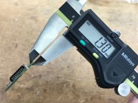
@trag  That's the problem!  I used a pair of precision Japanese digital calipers to measure my three ROMs as follows (measuring thickness at the pads):

SE/30 Stock ROM: 1.26mm (no issues)

IIsi ROM: 1.30mm (no issues, see photo below)

ROM-inator II MEGA: 1.13mm (occasional freezes, especially after having warmed up)

IMG_1507.jpg

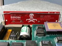
Previously, @Bolle said he added solder to BOTH SIDES of the ROM-inator only to find it made matters worse for him.  He then suggested to me to add solder only to the BACK side, which I interpret as "the cross-bones side" (i.e., opposite the chip side). I then asked him why adding solder to the chip-side pads wouldn't be better, but he never replied.  I asked why because when I view my ROM's back side (crossbones) side pads, I see little nicks in them to indicate they've made contact, but when I view the chip-side pads, I don't see the little nicks.  

So I'm unsure what to do at this point.  But I do know that following the ROM-inator documentation (rubber bands, etc) does NOT work because you are just pushing on set of pads closer to the motherboard pins while creating a pin-gap on the opposite side.

Thoughts?

 
Last edited by a moderator:

Paralel

Well-known member
You're right, JDW. It's a problem that has no good solution. You need contact on both sides, so shifting to one side or the other, like with a shim or a rubber band is not a solution. A shim on each side leaves you in the same position you're in now, poor contact on either or both sides due to the board not being thick enough.

I think solder could work, you would just need to add solder, then subtract from it by removing very small layers, until you are within that tolerance range. It's a time consuming solution, but I honestly can't think of anything else. It's a nasty situation.

 
Last edited by a moderator:

trag

Well-known member
I would get some kind of adhesive strip -- even a mailing label cut to a narrow strip, and put that across one side of the pins.

That should add thickness, be more uniform, and it is easily reversible, if it does not work.

Later edit:   It occurs to me that a problem with the above idea may be that the strip might deform over time and pins press into it until it is no longer providing a spacing function.

 
Last edited by a moderator:

Bolle

Well-known member
I tried both ways and it just does seem to work better with solder only on the backside (actually tried solder on the front side first as well for the same reasons you stated earlier but I was wrong, it made things worse)

I guess it’s better to have the front side pushed evenly against the spring contacts because those are the main contacts.

The solder on the back more or less acts as a spacer to push it towards the contacts. You probably could stick something in there as well (I actually tried thick tape on the back of the whole SIMM and it did work ok-ish)


JDW

Well-known member
I have connected to a modern display using some random 10-dip adapter I purchased from eBay.  It works very well at 640x480 with millions of colors, or 800x600 60Hz with 256 colors using DIP positions 14679 on.  The monitor utility lists more resolutions up to 1024x768, but I was unable to get my monitor to sync with anything higher than 800x600.
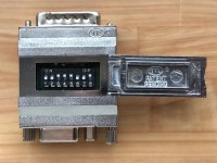
Thanks to the extreme kindness of @mx-v and to @trag for alerting me to that kindness in time, a UnimacFly adapter arrived in my possession today and cost me nothing but the shipping to Japan.  It only has 8 dip switches, not the 10 @joethezombie spoke of, so that aforementioned 14679 setting cannot apply to my UnimacFly adapter.  Here's what it looks like:

UnimacFly.jpg

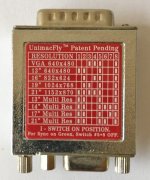
And on the back, it gives this guidance (only 1 "VGA" 640x480 setting, but note that the 13" setting is also 640x480 for some reason):

UnimacFly_Settings.jpg

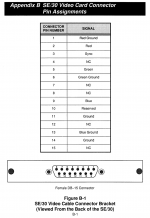
And here is the chart from the Micron Xceed MacroColor 30 manual:

MacroColor30HR_DB-15_to_VGA.png

My VGA color display is at the office and since this is Golden Week here in Japan I can't test until Monday, but I am quite curious how the DIP switches on this UnimacFly correlate to the 15 pins shown in Figure B-1 above.  In other words, if I flip 3-4-5-8 to be ON, what specifically does that do to the 15 pins?


trag

Well-known member
Some of the pins in the video connector are "sense pins".  They're unused for the video signal, but Apple used them for their resolution signaling scheme.   Probably the ones listed as NC on your pin out.

 
Last edited by a moderator:

JDW

Well-known member
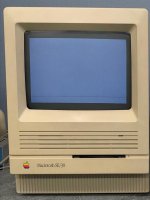
Well, I spent a couple hours testing my Micron Xceed MacroColor 30 PDS video card with my 17" VGA color display (LCD) and no matter what the DIP setting I use on the UnimacFly adapter, my VGA display is black (no signal).  I know the UnimacFy adapter works because before I tested my MacroColor30HR, I tested the adapter with my Color30HR card and it worked fine at different resolutions and DIP settings.  So again, it's my MacroColor30HR video card (with a bad VRAM or two) that won't display anything on my VGA monitor.  If I set the resolution in the MacroColor30 control panel to be 640x480, when I reboot with the VGA display connected, I get a contentless display on my SE/30's internal CRT like you see in this photo...
Mac.jpg

But if I change the resolution to 1024x768 and reboot with the VGA display connected (again with the MacroColor30HR video card), I get a completely black screen on my internal CRT.

Seems odd that the card would display video on the internal CRT (albeit with a vertical line artifact in some color and grayscale modes) but no video at all on an external display.

:-(

Any thoughts on this would be appreciated.

Next...

Regarding my UnimacFly adapter when used with my Color30HR video card, like I said, it has no problems displaying video on both the internal CRT and my 17" VGA color LCD display.  And while I can set the resolution via Xceed control panel and reboot and get that resolution, I am curious when the DIP settings are needed.  It seems I can get different resolutions without even changing the DIP switches at a lot of the time.  For example, I can set the DIP switches to be 1-2-5-7-8 ON (17" Multi Res setting on the UnimacFly) and then choose 1024x768 in the control panel or 640x480 in the control panel and have those resolutions display just fine.  So I'm curious what the 640x480 DIP setting is for since the other DIP settings seem to work too.  AND, why is there a "VGA 640x480" DIP setting and also a '13" 640x480' setting too?


Bolle

Well-known member
If I set the resolution in the MacroColor30 control panel to be 640x480, when I reboot with the VGA display connected, I get a contentless display on my SE/30's internal CRT like you see in this photo...


This means the card detected an external screen and you have your main monitor set to the external one. For some reason your monitor doesn't pick up the signal. 640x480 doesn't necessarily mean VGA so the card may be sending a refresh rate that is not supported by your display or it might do sync on green, which is not supported by all monitors.

The DIP settings are needed if your screen is not multisync capable but your video card is. Not sure if the MacroColor30 even reads the sense lines. If a card does not care about the sense lines the settings on the adapter are more or less meaningless.

What kind of external display you got? Did you check what resolutions and refresh rates it supports and if it does SoG?

I am pretty sure your display is the problem here.

 
Last edited by a moderator:

JDW

Well-known member
 My 17” LCD display is at the office and since I’m no longer at the office I cannot give you a specific reply about the details of my display until tomorrow. But the fact remains that when my Color30 HR video card (not my Macro card) is inside my SE/30, it works fine with my monitor! Why would that be  if indeed my “monitor is the problem“? 


Bolle

Well-known member
One card might be doing sync on green and the other one has separate sync and only one of those could be supported by your monitor.

That's what we need to know at first. A good (older) multisync display will support about anything you throw at it. Good ones will also tell you what kind of resolution and refresh rate they detected even if they can't display it.

The other thing to check is to see if the card actually outputs a video signal. It is detecting that there is a monitor connected or otherwise you wouldn't get the gray screen when a monitor is connected. (btw: does the Mac boot up when it displays that screen?)

Do you have a way to probe the output lines if there are any signals present when a monitor is connected?


JDW

Well-known member
Yes, I think the Mac boots up as per what my ears can hear, but there's no way to confirm it since I cannot see anything on any display.

Yes, I have the equipment necessary to probe pins, but what should I be looking for in terms of voltages and pulses, and on which pins?

And as an aside...

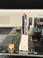
I finally got my ROMinator II Mega to be secured in the slot without having to add any solder. What I did was just use a thicker and therefore stronger paperclip to apply sufficient force to the top of the ROM to push it hard to the left as shown in the photo below:

IMG_1535.JPG

IMG_1534.JPG


JDW

Well-known member
@Bolle

The display I have been using (a picture of which is shown on page 1 of this thread) is a Japanese "Logitec" brand display that was discontinued back in 2005.  Here's a translated web page showing the specs:

https://translate.google.com/translate?sl=ja&tl=en&u=https%3A%2F%2Fwww.logitec.co.jp%2Fproducts%2Fmonitor%2Flcmt175as.html

17" SXGA 1280x1024

Sync Horizontal: 30 KHz to 82 KHz Sync Vertical: 56 Hz to 77 Hz 

Resolutions and frequency presets listed on the above web page.

But again, I must repeat the questions in my previous post.  I'm not sure how to test this.  You see, my CRT display works as normal UNTIL I connect the VGA display.  If I connect the display when the Mac is already booted, the CRT display remains but contrast drops in half, and nothing displays on the external monitor.  But if I cold-boot with the VGA display connected, then my internal monitor displays nothing (because it becomes a second monitor), and nothing at all displays on my VGA display with my MacroColor30HR card, but video displays fine with my Color30HR card.  What this means is, if all I do is try to probe individual pins, I doubt I would get a signal because the video card would detect that no monitor is connected.  So to test the signals, I would need to connect the monitor, then do a cold boot, and then test.  But again, I am not sure what signals I am looking for.  I could use my Color30HR's signals as a reference, but since I don't know what to look for, should I find a difference in the signals between the two video cards, can one say that difference is "the problem" or in fact just a difference in signals between the two cards.  All said, I have test equipment, but I don't know the best way to use that equipment (scopes, meters, etc) to test because I don't know what signals I need to be looking for and on what pins.  If you do, please let me know.

Thanks.


JDW

Well-known member
Not sure if my VGA 17" display supports "Sync on Green" but it doesn't seem to.  I put my Color30HR card back into my SE/30, then switched on only 3 & 4 for VGA on my UnimacFly adapter, leaving 5 & 8 OFF because the adapter says to when using "Sync on Green."  When I flip power on, I get the standard gray screen on my CRT but nothing appears on my VGA display.  So that seems to show this display doesn't support Sync on Green.  Not that it really matters anyway because I don't think either Xceed Card outputs "Sync on Green."

So the question is, could the bad VRAM which causes the vertical line in some color modes on the internal CRT completely prevent communication with an external display?  

Again, I don't know what I'm looking for when testing signals on my MacroColor30HR card's external monitor output, so if anyone does know what I should look for and on what pins, please let me know.  But even then, let's say I test and find I am not getting the signals I should.  Again, could that be the result of the bad VRAM?

Thanks.


Bolle

Well-known member
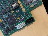
I think I found the issue with external video on your card:

IMG_1778.jpg

The connector still plugs in no problem, so you probably didn't notice this. Also I can't imagine this happened in shipping.

Straightened the bent pin and got a nice picture on my external screen using a VGA adapter without switches.

The line is visible on an external screen as well btw. More on that in the other thread.


JDW

Well-known member
@Bolle You have a sharp eye.  Black connector, bottom left pin, it would seem.  I never noticed that!

I got your PM about the vertical line problem possibly being related to the ROM being partly bad.  That's interesting because I had long thought it was one of the VRAM chips.

 
Top