• Updated 2023-07-12: Hello, Guest! Welcome back, and be sure to check out this follow-up post about our outage a week or so ago.

Running the Thunder II 1360 at 1600x1200

Bolle

Well-known member
You're right, that 0400 should have been 0404...

So for horizontal you have:
000E 0014 00B4 00D3
And vertical:
0003 0004 0404 042A

All values have to be seen in respect of the beginning of the sync period, which always starts a new cycle.
To take vertical as an example you start at line 0, Vsync will become active and stay active for the duration of 3 lines. Another line later (or 4 lines from the beginning of the current frame) the blank period will end and the active area will start. 400(hex) lines later the active area ends and blanking will start. Another 0x42A-0x404=0x26 blank lines will be counted before the next cycle starts.

The horizontal parameters work the same way, except that you have to multiply all values by a certain factor defining how many active pixels there are for each clock interval - it's likely the active pixel per clock interval can be set on those cards so the video clock always stays in a certain frequency range.
 
Last edited:

nyef

Well-known member
There can be off-by-one issues all over the various timing register values due to latency issues between recognizing that the sync state machine needs to change state and actually changing the state (the vertical sync state machine needs to transition synchronously to scanline boundaries, so the signal that a transition is necessary needs to ready ahead of time, and similarly for the horizontal sync state machine). The various back and front porch widths can be adjusted to shift the position of the active area to some degree. And if the clock multiplier can't get the pixel clock exactly right, tweaking the various timing parameters can generate a signal that's close enough that most monitors will give a usable display.

If I had the hardware for this and were looking to nail things down precisely, I'd probably use an oscilloscope to find the pixel clock and monitor it as I tried different values for the suspected clock scalar, then do the same again with the sync and video signals (well, okay, the green video signal, since most Mac cards are sync-on-green) while adjusting the mode timing values.
 

MacOSMonkey

Well-known member
@jmacz - In an earlier post, I think I mentioned about adjusting the vertical value. You have a working config at 1280x1024 with the caveat that it you can't see the entire vertical area. However, it should be easy to find the SMT02 timing offset in the sRsrcs.

Try the following:
1. Take a known config on your board
2. Use Macsbug to dump from [super slot + $c000000] (which I think is the SMT02 offset) - maybe SMT02S doesn't match, but it should be close
3. Compare the values you see in Macsbug with the values in the sRsrc and try to align them
4. Once you align them, then you know the SMT02 timing data offset in all sRsrcs on your board

From my earlier post, you know that the 1st long in the sRsrc is the length and the 1st byte is likely the clock select, since it tracks configs of the same resolution. Other than that, the timing data should be close to the start of the sRsrc - 20 bytes? 30 bytes? The Macsbug test will show the exact offset.

Also, SMT02 picked up where the TI TMS34061 left off from the earlier Spectrum boards -- Spectrum/8, Spectrum/24, etc. SMT01 showed up in Spec/8 Series III, Spectrum/24 III and similar generation boards. Anyway, I'm pretty sure that the register order in SMT01/2/2S is the same as the order in TMS34061 -- just because it was the starting point for the designs and there was some degree of parallelism.

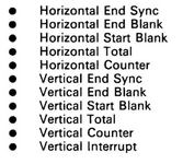
Here is the register order for the TMS34061:
TMS34061Registers.png
The only thing to watch out for might be the counters. But, that's also something that should be easily observable. Just do multiple reads from whatever the address is: $Scxxxxxx and if the values never change, then you know there are no counters in the way. I don't think there are. Otherwise, if you do see any values increasing/rolling over, then the counters are present and they will further show the H/V alignment. But, in the sRsrc, those values would either be 0 or not present.

Your 1280 timing sync'd up. So, the first thing to do is figure out VTOT. It's basically going to be VRES (1024)+VEB+VES (I think). From there, VSB is going to be VRES+VEB+1 (blanking starts -- at the bottom of the screen -- on the next line after the visible area).

You know the starting config and once you know the VTOT position in the timing data, you can modify that value and then calculate a new VSB...or just start increasing the VSB value by +1 at a time until you see everything. You might also need to decrease the VEB by -1, etc. Just make sure you don't trip up on VES. VEB should never be less than VES.

Anyway - if you get VTOT right and adjust VSB, you should be close to the finish line and should hopefully be able to see everything at full vertical resolution.
 

Bolle

Well-known member
Anyway, I'm pretty sure that the register order in SMT01/2/2S is the same as the order in TMS34061
The parameter sets from the ROM look identical at least, that's why I was able to immediately make sense of them from our adventures with the TMS34061 on the SE/30 card.

Edit: also Horizontal End Sink, because it's totally relevant.
HorizontalEndSink.png
 

jmacz

Well-known member
@Bolle ok cool, makes sense now with the correction. So theoretically, I should be able to tweak the existing 1280x960 row in the following manner (changed sections marked with a dash over it):

Code:
SuperMatch High-Res 20 Color
                                    -------- -------- -------- --------
00000076 1F320000 50020600 4F010101 000F001E 00BE00C9 0002002D 03ED03F0 FFFFFFFF 00E7FFFF 0000FFFF 00000000 00000000 00404000
05508005 05000000 E0C0B576 256D0000 00000040 00810073 00000500 03C09500 53757065 724D6174 63682048 6967682D 52657320 32302043 6F6C6F72 00

to be:
                                    -------- -------- -------- --------
00000076 1F320000 50020600 4F010101 000E0014 00B400D3 00030004 0404042A FFFFFFFF 00E7FFFF 0000FFFF 00000000 00000000 00404000
05508005 05000000 E0C0B576 256D0000 00000040 00810073 00000500 03C09500 53757065 724D6174 63682048 6967682D 52657320 32302043 6F6C6F72 00

We still don't know how the 1F and 0550 is utilized but given the pixel clock in the VESA spec is the same for 1280x960 and 1280x1024, I'm hoping the existing values are fine.

And then to @nyef's point, I may have to tweak the timing values slightly to dial it in.

But I am hoping that @MacOSMonkey might be able to answer my earlier question in post #99 about how the above is used? I think changing the above (if we can get it working) is enough if I choose "SuperMatch High-Res 20" during initial boot, as long as I don't make changes using the CDEV. But if I do select a monitor/resolution in the CDEV later, it might undo the changes as it's not clear to me whether the CDEV uses the above?

@MacOSMonkey will also try your suggestions once I get the board (and my Mac) in front of me. Won't be back to try any of this for another week or so. I've only been playing with the ROM as that's all I have access to at the moment.
 

MacOSMonkey

Well-known member
Regarding the sRsrc format, for the Stock 1280x960, here is what I see by attempting pattern-matching vs. obvious data types and working forwards/backwards, etc.:

original data: [00000076 1F320000 50020600 4F010101 000F001E 00BE00C9 0002002D 03ED03F0 FFFFFFFF 00E7FFFF 0000FFFF 00000000 00000000 00404000
05508005 05000000 E0C0B576 256D0000 00000040 00810073 00000500 03C09500 53757065 724D6174 63682048 6967682D 52657320 32302043 6F6C6F72 00]

00000076: sRsrc length (from earlier post)

1F: clock select (from earlier post)

looking for start of SMT -- HES should be a low value, then HEB, HSB, HTot, [?], VES, VEB, VSB, VTOT and they must be word values that make sense.

320000 - working backwards from the start of SMT and likely BSR, these must be board-related - there were 2 registers, but there is a byte missing - oh frequency select above - right. So -- should probably look like this:

Reg 1:
1F - clock select
32 - ? (do more comparisons on this one)

Reg 2:
00 - ?
00 - ?

I guess that makes sense.

BSR -- see reasoning below - 8 bytes and obvious start of timing data for SMT...but ??
50
02
06
00
4F
01
01
01 (this data doesn't fit timing values, so may be BSR - it had 8 byte registers)

next block of data that looks like valid SMT word timing values (000F 001E 00BE 00C9 0002 002D 03ED 03F0 FFFFFFFF 00E7FFFF 0000FFFF 00000000 00000000 00404000
05508005 05000000 E0C0B576 256D0000 00000040)

SMT02 offset in the sRsrc -- So -- byte 16, or $10 is the start of SMT02 data -- but I guess you already figured that out
000F (15) - must be HES -- first low word value
001E (30) - HEB
00BE (179) - HSB
00C9 (201) - HTOT
0002 (2) - must be VES - looks right
002D (45) - VEB (low number)
03ED (1005) - VSB = VRES(960) + VEB(45) - seems OK, off by 1?
03F0 (1008) - VTOT = VRES(960) + VEB(45) + VES(2)

No apparent counter registers in the timing block above.

Other SMT02 registers - this is the "deer with no eyes" section.
FFFF
FFFF
00E7
FFFF
0000
FFFF
0000
0000
0000
0000
0040
4000
0550
8005
0500
0000
E0C0
B576
256D
0000
0000
0040

Next part: 00810073 0000

Must be SQD, since it had 3 registers, it's the only thing left and the sRsrc/name info follows. So...ruling out, etc. Best fit. Easy enough to check - write garbage there and if the acceleration is all screwed up, then you know. :D
0081
0073
0000

This is the ending part, which is pretty easy based on the obvious data:
0500 1280 hRes
03C0 960 vRes
95 master sRsrc ID
00 padding probably
53757065 724D6174 63682048 6967682D 52657320 32302043 6F6C6F72 00 [term]
Supe rMat ch H igh- Res 20 C olor


So, then the question is...does your modification make sense re: timing? Let's see -- as you mention, the timing should be similar.
000E/HES: 14 (you could try starting with the same H values and just modify V)
0014/HEB: 20
00B4/HSB: 180
00D3/HTOT: 211
0003/VES: 3 (I would leave this value at 2 -- it's going to be SMT-related)
0004/VEB: 4 (no - back porch is too small (may be slammed against the top of the monitor-- proportionally, maybe 42 vs. 45 (6.7% decrease) -- or ask Douglas Adams :D )
0404/VSB: 1028 (no - 1024 + 42 -- 1066, as above or maybe 1067 -- try $042A)
042A/VTOT: 1066 (no - 1024 + 42 + 2 +1 = 1069 -- so $042D)

These are my best guesses -- maybe not right -- you will have to play around with it and see.

Also, in your version, it doesn't look like you modifed the screen resolution at the end of the sRsrc.
Vertical $03C0 (960) should be $0400 (1024). This issue may be why you don't see the full height...and it should match the resolution shown in all the other related sRsrc table entries (bit depths, etc.)

OK - that's the best I can do -- hope it helps. I have to find my board...but maybe the above will help you get closer to the finish line. I think I feel like I have a video hangover. :D

Oh - the other questions --

Loading from SuperVideo -- maybe...but probably in the ROM. SuperVideo shows all of the available configs. And, when you use SuperVideo to change a config, it copies the data into PRAM. So, if you trace it after setting it, you can see where the config data is coming from. Or, look at SuperVideo with ResEdit when you open that screen and see what resources it is getting to track down any that might have video configuration data. But, it's possible that SuperVideo 3.0 could be inserting something into PRAM. Check the ROM carefully.

In terms of undoing things, SuperVideo will just grab what's in ROM, so it shouldn't affect what you've done unless that specific timing configuration has been replaced in software...but seems unlikely, since it would have had to work from ROM at FCS.
 
Last edited:

eharmon

Well-known member
But I am hoping that @MacOSMonkey might be able to answer my earlier question in post #99 about how the above is used? I think changing the above (if we can get it working) is enough if I choose "SuperMatch High-Res 20" during initial boot, as long as I don't make changes using the CDEV. But if I do select a monitor/resolution in the CDEV later, it might undo the changes as it's not clear to me whether the CDEV uses the above?
I suspect it just uses those timings for every monitor, but I'm not really sure. Since they're not stored in the sPRAM anywhere, and all resolutions do work at boot after configuration, I think it must use the same timings for any compatible display.
@eharmon did you figure out where the data table is that the $42 (in your case) references?
Not yet. I want to modify RF to see if it becomes more obvious. I strongly suspect it's the same table we're all looking at currently, as nothing else makes much sense...we'll see.
 

MacOSMonkey

Well-known member
SuperMac had custom timings for Apple, RasterOps, Radius, et. al. Everyone had to have their own proprietary timings to make things hard for consumers. But...SuperMac supported most/all of them. 16", 19", 21", Apple Portrait, MultiSyncs, etc.

(and they were usually all in ROM)
 

eharmon

Well-known member
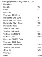
Alright, I have RF decoding this data.

Pushed to a temporary branch at https://github.com/eharmon/rom_fiend/tree/thunder_ii, because it's hardcoded to assume these resources are timing data (trying to figure out how to detect that better).

Should make confirming changes a little easier than skimming hex visually.

Let me know if any corrections are needed.
1722397054244.png
 

eharmon

Well-known member
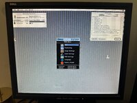
Partial success! I modified the timing and Video Mode entries for 1280x960 and configured my monitor as a High-Res 20.

Both the OS and my monitor see 1280x1024, with no framebuffer scrolling. It's not quite pulling sync though, the whole thing is slightly too large and spills from both sides, and I think I'm losing a couple lines on the bottom.

I'm surprised it lost the width...I'm getting all the pixels but the monitor can't lock into the right clock to size the width.

Code:
000F001E 00BE00C9 0002002A 042A042D FFFFFFFF 00E7FFFF 0000FFFF 00000000 00000000 00404000 05508005 05000000 E0C0B576 256D0000 00000040 00810073 00000500 0400

FWIW, the clock on the 1280x960 entry is weirdly faster than the rest...maybe contributes.

But it's close!
IMG_3102.jpeg
 

eharmon

Well-known member
Some other observations:

- I hooked up my Extron scaler and that does pull in sync fairly well. Still a few pixels of cropping at the bottom but it's not bad at all. So we're not far off from fairly compatible timings.
- At first boot, the bottom of the frame (probably ~64 pixels tall) is uninitialized data. As soon as the 1-bit grey paints the problem is fixed and doesn't appear to return, but some of those other registers must control VRAM initialization for the framebuffer.
- It appears the timing list drives the "select a resolution on boot" flow. I'm guessing that's what the sRsrc ID is for -- to make sure it configures the right setting for the OS to use as well. This is where the strings listed in the timings are used as well.
- I'm still not sure how the sPRAM maps to this timing data.
- Before someone says it, yes I need to put more memory in my Q700 😛.

Unfortunately my 1600x1200 monitor is in storage, so I'll have to come back to trying some of those timings!

Nice sleuthing everyone!

EDIT: Er, no, I'm an idiot. I read my own post from the first page again and the sPRAM Physical Resolution ID + 200 maps to the correct timing sResource.
 

jmacz

Well-known member
In the Radius Thunder 4 GX 1360 ROM that @Bolle posted, it looks like the timing data is located around offset 0x05940:

Code:
00E400E4 00C800AC 04B00640 002B007B 020B0215 00020025 04D504D8 000500F0 001BF012 04B00640 002F0083 0213021B 00020030 04E004E1
00050030 001B7C0E 04000550 00210063 01B701C1 00020025 04250428 000500F0 0017EC17 04000500 001F0057 0197019F 00020024 04240427
000500F0 00153C10 04000500 002F0057 0197019F 0003002E 042E0435 00050030 000FE41F 03660480 002B005B 017B017F 00020023 0389038F
000500C0 000D1813 03660480 002B005B 017B017F 000E002B 03910397 000500F8 000D1813 03660480 001F0043 0163016B 00020029 038F0392
000500F0 000DDC21 03660480 001F0043 0163016B 00020029 038F0392 00050030 000DDC21 03660480 00290045 01650175 00060027 038D0393
000500F0 000DDC21 03660480 0021005B 017B017F 00020021 03870387 000500C0 000D1813 03270420 00270053 015B015F 0002001D 03440344
000500F0 00094C19 03000400 00170043 0143014B 00020020 03200323 000500F0 00057020 03000400 00130037 0137014B 0002001F 031F0322
000500F0 00057020 03000400 00210045 0145014B 00050022 03220325 000500F0 0002E415 03000400 00210049 0149014F 00050022 03220325
00050030 0015A896 03000400 00210049 0149014F 00050022 03220325 000500F0 0015A896 02700340 000F0047 0117011F 00020028 0298029A
000500F0 0011E49D 02700340 0017003F 010F0117 0002001A 028A028D 000500F0 000F1891 02700340 000F0033 01030111 0002001F 028F029A
000500F0 000FC89D 02700340 001F002F 00FF0107 0005001F 028F0299 000500F3 000D6498 02580320 001F0035 00FD0107 00030019 02710273
000500F3 000570A0 03660280 00130027 00C700CF 0002002C 03920395 00050030 0011E49D 01E00280 00170023 00C300C7 00010021 0201020C
000500F0 000FA91D 01E00280 000F0027 00C700D7 00020029 0209020C 000500F0 00132510 02328101 0A0001A0 83010300 019A8701 03000194

It's not aligned properly (ie. each row is NOT a record).. but each record seems to be around 56 bytes. If you look at the 3rd column of 4 bytes, you will see the resolutions beginning with the first row being 1600 x 1200. Columns 6 and 7 look like vertical timing data.
 

MacOSMonkey

Well-known member
Hi eHarmon - It looks like you're missing 1 clock on either side of the horizontal display. So, reduce HEB by 1 and add 1 to HSB. Adjust HTOT as needed.

For the clipping at the bottom, you can try adding 1 to VSB. If that doesn't work or isn't enough, then you may have to shift the entire image up by subtracting 1 from VEB. Adjust VTOT as needed.

You can repeat this process to calibrate the timing alignment, providing that the monitor still syncs.

The other problem could be the HES/VES values -- for example, if there is not enough time to get to the next row start or line -- but it looks like it might be blanking.

Some Edits:
I say 1 clock above re: visible area because it looks like 16 pixels are missing on either side -- so maybe 1 clock or 4, depending on the multiplier. If +/- 1 moves blanking by 4 pixels, then try +/- 4.

And if none of the above works, then put it on an oscilloscope and check vs. Dell's expected monitor timing spec. The SMT data likely starts at $Sc000000 -- so, given that the OS bounds are now correct, you can just poke new word values into the registers at the correct reg offsets in real time without screwing around with sRsrcs. Then, you can quickly see if the timing comes into alignment.

ps. I checked out the github page. Nice job - looks like an interesting tool. It would be helpful to add a link to this thread as a citation to document the origin for the Thunder II implementation so that others can understand and follow the work.
 
Last edited:

jmacz

Well-known member
In the Radius Thunder 4 GX 1360 ROM that @Bolle posted, it looks like the timing data is located around offset 0x05940:

Code:
00E400E4 00C800AC 04B00640 002B007B 020B0215 00020025 04D504D8 000500F0 001BF012 04B00640 002F0083 0213021B 00020030 04E004E1
00050030 001B7C0E 04000550 00210063 01B701C1 00020025 04250428 000500F0 0017EC17 04000500 001F0057 0197019F 00020024 04240427
000500F0 00153C10 04000500 002F0057 0197019F 0003002E 042E0435 00050030 000FE41F 03660480 002B005B 017B017F 00020023 0389038F
000500C0 000D1813 03660480 002B005B 017B017F 000E002B 03910397 000500F8 000D1813 03660480 001F0043 0163016B 00020029 038F0392
000500F0 000DDC21 03660480 001F0043 0163016B 00020029 038F0392 00050030 000DDC21 03660480 00290045 01650175 00060027 038D0393
000500F0 000DDC21 03660480 0021005B 017B017F 00020021 03870387 000500C0 000D1813 03270420 00270053 015B015F 0002001D 03440344
000500F0 00094C19 03000400 00170043 0143014B 00020020 03200323 000500F0 00057020 03000400 00130037 0137014B 0002001F 031F0322
000500F0 00057020 03000400 00210045 0145014B 00050022 03220325 000500F0 0002E415 03000400 00210049 0149014F 00050022 03220325
00050030 0015A896 03000400 00210049 0149014F 00050022 03220325 000500F0 0015A896 02700340 000F0047 0117011F 00020028 0298029A
000500F0 0011E49D 02700340 0017003F 010F0117 0002001A 028A028D 000500F0 000F1891 02700340 000F0033 01030111 0002001F 028F029A
000500F0 000FC89D 02700340 001F002F 00FF0107 0005001F 028F0299 000500F3 000D6498 02580320 001F0035 00FD0107 00030019 02710273
000500F3 000570A0 03660280 00130027 00C700CF 0002002C 03920395 00050030 0011E49D 01E00280 00170023 00C300C7 00010021 0201020C
000500F0 000FA91D 01E00280 000F0027 00C700D7 00020029 0209020C 000500F0 00132510 02328101 0A0001A0 83010300 019A8701 03000194

It's not aligned properly (ie. each row is NOT a record).. but each record seems to be around 56 bytes. If you look at the 3rd column of 4 bytes, you will see the resolutions beginning with the first row being 1600 x 1200. Columns 6 and 7 look like vertical timing data.

I didn't see the obvious second set of resolutions in the same dump above. So each record looks to be 28 bytes, not 56 bytes... red columns below showing the resolutions.. green box representing a single record (best guess based on the appearance of the data). After the resolution, first set of 8 bytes seems to be horizontal timing, second set of 8 bytes seems to be vertical timing, not sure about the third set of 8 bytes.

Screenshot 2024-07-31 at 10.19.05 PM.png

Resolutions:
  • 1600x1200 - 2 records
  • 1360x1024 - 1 record
  • 1280x1024 - 2 records
  • 1152x870 - 6 records
  • 1056x807 - 1 record
  • 1024x768 - 5 records
  • 832x624 - 4 records
  • 800x600 - 1 record
  • 640x870 - 1 record
  • 640x480 - 2 records
Both ROMs (1360 and 1600) seem to have the same table.
 
Top