Kai Robinson
Well-known member
So - as the title explains, this is designed to save as many Mac SE's as possible. So many have died thanks to the stupid PRAM battery on the board, and with the SE being a 2-layer PCB with just through hole components, it's actually one of the easiest to save. So - how do you reproduce a PCB?
First, get a Mac SE PCB - in my case a 'dead' board from eBay for €29 - thanks, random spanish man!
Then, you get to work desoldering. Literally EVERYTHING. Not a single component must remain! However, 30 year old solder and my ZD-915 desoldering station caused a handful of through holes to just pull out of the board, or some traces would come up with it. I found that pre-heating the joint, with a little flux (AmTech RMA-223), would make the solder melt a lot cleaner when you use the ZD-915 desoldering gun. You must use a lot of heat, on these boards. For those joints that have been corroded, you must flood the area with flux, heat from both sides, then try and move the pin using a soldering iron (i find 420 degrees C suitable, with a standard flat tip) before trying to use the desoldering gun. Sometimes it won't always come out of the joint, in which case reflood with flux, and attack it with desolder braid. I use 2.0mm GootWick, which is fantastic stuff (thanks to Louis Rossmann for the recommendation).
As part of this process, I made a list of the parts that you need to save, and the ones that you can ditch. Obviously, all the custom Apple ones are a must - the rest are either still available, or are available as new-old-stock or pulls.
So - here's what you need to save:
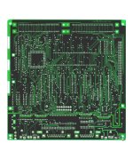
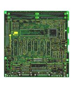
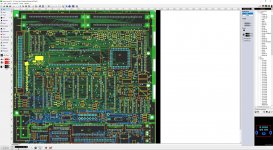
Once you've saved all those parts, it's time to get scanning! 800 to 1200dpi on your scanner. If your scanner bed cant quite fit the whole thing on, scan one side, then rotate 180 degrees, scan, flip the image, then you can merge the images in photoshop. My scanner clips about 5mm off, so i use this method.
There will be a part 2 to follow...but any questions so far?
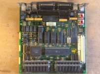
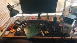
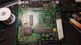
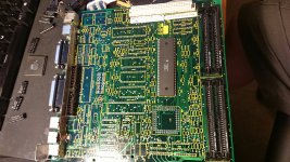
First, get a Mac SE PCB - in my case a 'dead' board from eBay for €29 - thanks, random spanish man!
Then, you get to work desoldering. Literally EVERYTHING. Not a single component must remain! However, 30 year old solder and my ZD-915 desoldering station caused a handful of through holes to just pull out of the board, or some traces would come up with it. I found that pre-heating the joint, with a little flux (AmTech RMA-223), would make the solder melt a lot cleaner when you use the ZD-915 desoldering gun. You must use a lot of heat, on these boards. For those joints that have been corroded, you must flood the area with flux, heat from both sides, then try and move the pin using a soldering iron (i find 420 degrees C suitable, with a standard flat tip) before trying to use the desoldering gun. Sometimes it won't always come out of the joint, in which case reflood with flux, and attack it with desolder braid. I use 2.0mm GootWick, which is fantastic stuff (thanks to Louis Rossmann for the recommendation).
As part of this process, I made a list of the parts that you need to save, and the ones that you can ditch. Obviously, all the custom Apple ones are a must - the rest are either still available, or are available as new-old-stock or pulls.
So - here's what you need to save:
- SIMM Sockets - IMPOSSIBLE TO GET - desoldering these needs HEAT as there are a lot of connections to the ground plane. Pre-heat the joints, maybe add a dab of proper Kester 63/37 eutectic LEADED solder (none of that RoHS crap), flood with flux.
- PDS Socket - Amphenol/AMP/AVX DIN-41612 3-row, 96-pin connector (Style-C) - Available new, but still worth reclaiming as sifting through the minute variations of parts is an arse...
- Inductors - probably easy enough to get new ones, but ehhh, they don't really break, and they fit fine.
- AM26LS30's - NLA, only available as NoS or Reclaimed
- AM26LS32's - Available new, but still worth reclaiming
- MC3488A - NLA, only available as NoS or Reclaimed
- RTC Chip - Custom Chip - maybe possible to clone using pin-compatible ATTiny85
- ADB Chip - Apple branded PIC16CR54 - maybe possible to re-produce/clone
- GLU Chip - Apple branded PAL16L8 - maybe possible to re-produce/clone
- BBE Chip - Custom Chip
- NCR5830/AM58C30 SCSI Chip - NLA, only available as NoS or Reclaimed
- WIM/SWIM Floppy Chip - Custom Chip
- Hi & Lo ROM Chips - Toshiba TC531000CP MASK ROM's - Reclaim & reuse, but these are the same pinout as 27C512, but adds A16 in place of VPP pin - you can use 27C1001's on an adapter - doug brown made a similar setup with a built in ROM disk for the Mac Plus.
- 74LS245 - Available new, but still worth reclaiming - replace with CY74FCT245ATPC or CD74FCT245E
- 74F257 - Available new, but still worth reclaiming - replace with CD74ACT257E
- DB19 Connector - NLA, only available as NoS or Reclaimed. These are a bastard to get out cause the lugs are soldered. I found that pre-heating the joint first, filled with flux, then pressing hard into the pad with the desoldering gun, waiting til you see the solder go molten, you can often schlorp out the majority of the solder and then tidy up with wick afterwards.
- Passives - REPLACE ALL - use high tolerance metal film resistors & nichicon or panasonic electrolytics. Maybe try and save the PLCC Socket if you can. remove it cleanly - sometimes the pins pull out but they can be put back in if you're careful.
Once you've saved all those parts, it's time to get scanning! 800 to 1200dpi on your scanner. If your scanner bed cant quite fit the whole thing on, scan one side, then rotate 180 degrees, scan, flip the image, then you can merge the images in photoshop. My scanner clips about 5mm off, so i use this method.
There will be a part 2 to follow...but any questions so far?


Last edited by a moderator:

