GnatGoSplat
Well-known member
I've always loved the looks of the Quicksilver G4 and hated the looks of PC cases. When it came time to build a new PC, I decided I would do what several before me have done - build one into a Quicksilver G4 case. Around 2006, I bought a complete, but gutted Quicksilver case from eBay. I'm lazy and procrastinate a lot, so I didn't get around to starting this project until last Fall (only 5yrs later, that's actually pretty good for me considering I have unfinished projects dating back 13yrs).
I have seen this done many different ways, involving cutting corners off of DVD drives and relocating capacitors on the motherboard. I'm addicted to upgrading and replace drives and motherboards on an almost annual basis, so I found this unacceptable. Requirement #1: Everything must bolt in and fit as perfectly as it would in a regular PC case. No drives or motherboards will be modded or their warranties voided!
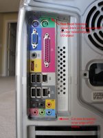
Hardest part was cutting the hole for the I/O shield. I used a Wizard rotary tool (B&D's version of the Dremel) and Dremel cutting discs. The fiberglass reinforced ones work much better. I didn't like this part because it made lots of dust and took quite a bit of time and a lot of test-fitting the I/O shield and motherboard. I used a respirator, but it didn't seal well against my face so I still managed to breathe some dust. There is not much room for error here because I wanted the I/O shield to snap firmly into place just like on a PC case. The I/O shield has to fit flush against the outer metal, so the inset part has to be cut slightly taller to allow this, as shown in the pic:
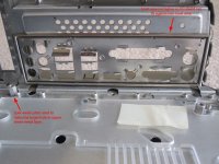
I was happy with the fitment, except the cut on the inset part is a little uneven. Oh well. There are no do-overs when it comes to cutting.
For mounting the new motherboard, some of the old standoffs had to be removed. Some people grind them off, I just grabbed each one with vise-grips and gently rocked them out.
There is one original standoff that is in the exact correct location for a full-sized Micro ATX motherboard. However, it has a mushroom-style head which I ground off, then drilled and tapped a hole. This standoff, along with a full mATX board and PCI card, makes for a perfect template for locating the other locations where new holes and standoffs need to go.
Standoffs I used were 3/8" tall which is the perfect height. I think they are M3 thread, and use standard PC case motherboard screws.
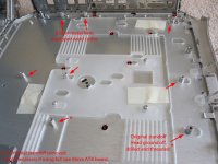
2 of the rear standoffs need to go where there is 2 layers of sheet metal. A spot weld cutter works perfectly for cutting through that top layer so the standoff can mount correctly. I used this spot-weld cutter: http://www.harborfreight.com/3-8-eighth-inch-double-sided-rotary-spot-weld-cutter-95343.html
The spot-weld cutter also worked great for making the oval holes in the latch plastic that the standoffs have to go through.
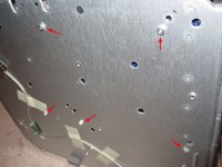
Standoffs are held in place with KEP nuts from behind. I also got them from eBay. They are nuts with a built-in lock washer.
Perfect fit! Here is the full-size Micro ATX board completely installed. It's an old LGA775 Core 2 Duo board that I was using as a template because a full-size board works best as a template. I did not use this board in the final build.
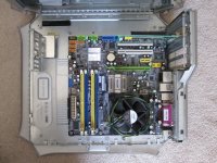
I went ahead and installed every standoff required to mount a full-size Micro ATX board, but as everyone who has attempted this project knows, a Micro ATX board interferes with the the optical drive. This illustrates how:
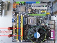
In order to avoid having to modify the ODD by hacking off a corner or relocate components on the motherboard, the easy solution is to use a smaller motherboard! Motherboard choice is key; whereas a full mATX board has a depth of 9.6", there are several Micro ATX motherboards that fall within the max 7" depth required to clear a 170mm optical drive. Unfortunately, most boards with <7" depth are also narrower width, lining up with only 3 holes on the backplane and use a Flex ATX standoff pattern. Those boards also usually only have 2 or 3 slots. Since I planned to use a gaming video card which are 2-slots wide, that would have left me with only 1 free expansion slot with the card. So I bought the only LGA1155 board I could find at the time that was <7" deep and full 9.6" wide, the Jetway MIH61M-DU3. This board has only 3 slots, but it lines up with 4 holes on the backplane since there is a slot-width empty space between PCIe x16 and the nearest PCIe x1 slot. That meant I was able to use my 2-slot wide gaming card while having both x1 slots available. Today, there are other LGA1155 boards that are both <7" deep and 9.6" wide, like the ZOTAC H61MAT-A-E, Gigabyte GA-B75M-D3V, or GA-H61MA-D3V (the last one would be my personal choice if I were doing this today). Most modern optical drives are 170mm, I don't believe there exists a shorter motorized tray style drive. LG lists theirs at 165mm, but they are really 170mm as LG for some reason doesn't include the bezel.
Maybe in the future, optical drives will become obsolete. Installing the extra standoffs for a full-size board gives me the freedom to use full-size Micro ATX if I want to ditch the ODD, but for now they will remain unused.
Slight modifications were required to the rear plastic bezel to accommodate the raised edge of the I/O shield and its additional width.
Here are a few silly things I did, because I'm eccentric and HATE waste. The original SensFlow fan is interesting because it has a thermistor to detect case temps and can vary its speed accordingly. I figured it would reuse it, but I wished it had a tach signal my new motherboard could read. So I found instructions on some guy's web page on how to add a tach. Unfortunately, I lost the URL so I can't credit him accordingly. The transistor and resistor I added for the tach are visible in this pic:
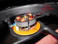
Siliconed in so they don't vibrate or move around.
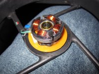
It's not real quiet, so spending $5 on a generic 120mm fan might have been the way to go, but this cost me nothing and did I mention I hate waste?
Most people reuse the front panel board, but bypass the circuitry by soldering wires. I couldn't stand to see all that Apple overkill technology go to waste! I reverse engineered the board and was able to determine that the MCU takes a PWM input and drives the power LED accordingly. So I built a little 555-timer based interface circuit to send PWM to it. The trimpot varies the pulse width so the LED brightness can be fine-tuned. The switches have a negative output which is what the motherboard needs. I added diodes so orientation of the power and reset connectors doesn't matter.
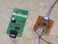
Back of my interface board, pretty messy because it's just a generic proto board.
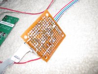
I even reused the original front panel cable, it plugs right into my interface board.
This is where the interface board goes. I attached it using nylon stick-on standoffs left over from a previous project.
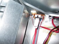
The next few pics are the inside of the completed project. Here the cut that had to be made to the ODD bracket can be seen. It won't clear ANY standard motherboard without that cut. I cut it with an angle grinder and cutting disc. WAY faster than a Dremel.
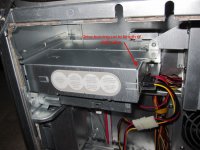
I attempted to route the SATA cable for the DVD burner the exact same way the original IDE cable was routed. It's a 1m ultra thin cable, about the same length as the original IDE cable. I got it here: http://www.newegg.com/Product/Product.aspx?Item=N82E16812816062
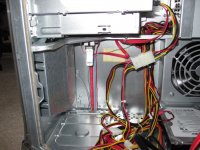
With the right power supply, there is no cutting or modification required at all to the case. In this instance, the right power supply is an ANTEC Basiq BP500U 500W. It has active PFC, good efficiency, and was pretty well reviewed here: http://www.hardwaresecrets.com/article/Antec-Basiq-BP500U-Power-Supply-Review/792
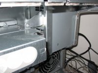
Even the screw holes in the bracket line up and screws that came with the case fit fine.
Front panel speaker is connected to the PC speaker header on the motherboard via a short adapter cable. I thought about just cutting off the original connector and put the PC speaker connector right on the original wires, but I thought some motherboards might have the PC speaker header further back so it's better to lengthen that cable instead of shorten it.
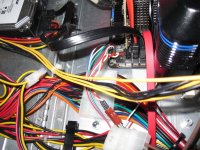
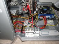
Here's an overall view of the inside. It's a messy rat's nest.
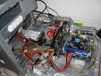
I did try to make it look a little neater with cable ties and such, but the PSU and extension cables I bought have the wires criss-crossing so it was hard to make it look neat. Yeah, it's the PSU's fault! Maybe it looks a little bit less messy from this angle. Or not.
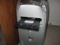
I removed the front cover from the DVD drive tray. The spring-loaded door on the case worked fine with it in place, but it made a noisy clatter when it opened and shut. Removing the cover quieted it down significantly.
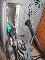
Rear of the finished project. As you can see, the ANTEC Basiq BP500U PSU fits perfectly, no mods required.
Closer view of the finished project. Looks 100% stock, just the way I wanted it.
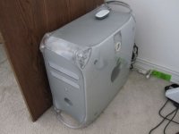
Overview of my setup. My wife would be embarrassed if she knew I shared a pic of that desk (it was free).
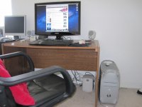
Monitor is a Samsung Touch Of Color 26". I bought it because the Apple 30" LCD is too expensive. The Samsung is made of clear polycarbonate, so it kinda-sorta goes with the clear poly theme of the Quicksilver case. Keyboard is Microsoft because my wife likes those "ergonomic" keyboards.
Yes, it appears to be running OS X Lion 10.7.4... but not really. It's VMware trickery! I don't know if the Jetway motherboard would run OS X natively or not. There would definitely be problems with the VIA audio. If I were to build this today, I would have chosen the Gigabyte GA-H61MA-D3V motherboard which has a whole lot better chance of running OS X natively due to using Realtek audio. No biggie though, the main purpose of this was as a budget gaming PC and it works awesome for that. Hackintosh wasn't my first priority. The Hackintosh VM does work really, really well though!
The setup consists of:
Jetway MIH61M-DU3 LGA 1155 motherboard
Kingston 8GB (2x4GB) DDR3
Intel Core i3 2130 3.5GHz dual core Sandy Bridge processor
MSI GTX460v2 video card
VBox 164e dual HDTV tuner card w/FM radio
ANTEC Basiq BP500U power supply
LG 22X SATA DVD-RW drive
Maxtor (Seagate) 500GB SATA 7200rpm drive
I have seen this done many different ways, involving cutting corners off of DVD drives and relocating capacitors on the motherboard. I'm addicted to upgrading and replace drives and motherboards on an almost annual basis, so I found this unacceptable. Requirement #1: Everything must bolt in and fit as perfectly as it would in a regular PC case. No drives or motherboards will be modded or their warranties voided!
Hardest part was cutting the hole for the I/O shield. I used a Wizard rotary tool (B&D's version of the Dremel) and Dremel cutting discs. The fiberglass reinforced ones work much better. I didn't like this part because it made lots of dust and took quite a bit of time and a lot of test-fitting the I/O shield and motherboard. I used a respirator, but it didn't seal well against my face so I still managed to breathe some dust.

I was happy with the fitment, except the cut on the inset part is a little uneven. Oh well. There are no do-overs when it comes to cutting.
For mounting the new motherboard, some of the old standoffs had to be removed. Some people grind them off, I just grabbed each one with vise-grips and gently rocked them out.
There is one original standoff that is in the exact correct location for a full-sized Micro ATX motherboard. However, it has a mushroom-style head which I ground off, then drilled and tapped a hole. This standoff, along with a full mATX board and PCI card, makes for a perfect template for locating the other locations where new holes and standoffs need to go.
Standoffs I used were 3/8" tall which is the perfect height. I think they are M3 thread, and use standard PC case motherboard screws.

2 of the rear standoffs need to go where there is 2 layers of sheet metal. A spot weld cutter works perfectly for cutting through that top layer so the standoff can mount correctly. I used this spot-weld cutter: http://www.harborfreight.com/3-8-eighth-inch-double-sided-rotary-spot-weld-cutter-95343.html
The spot-weld cutter also worked great for making the oval holes in the latch plastic that the standoffs have to go through.
Standoffs are held in place with KEP nuts from behind. I also got them from eBay. They are nuts with a built-in lock washer.

Perfect fit! Here is the full-size Micro ATX board completely installed. It's an old LGA775 Core 2 Duo board that I was using as a template because a full-size board works best as a template. I did not use this board in the final build.

I went ahead and installed every standoff required to mount a full-size Micro ATX board, but as everyone who has attempted this project knows, a Micro ATX board interferes with the the optical drive. This illustrates how:

In order to avoid having to modify the ODD by hacking off a corner or relocate components on the motherboard, the easy solution is to use a smaller motherboard! Motherboard choice is key; whereas a full mATX board has a depth of 9.6", there are several Micro ATX motherboards that fall within the max 7" depth required to clear a 170mm optical drive. Unfortunately, most boards with <7" depth are also narrower width, lining up with only 3 holes on the backplane and use a Flex ATX standoff pattern. Those boards also usually only have 2 or 3 slots. Since I planned to use a gaming video card which are 2-slots wide, that would have left me with only 1 free expansion slot with the card. So I bought the only LGA1155 board I could find at the time that was <7" deep and full 9.6" wide, the Jetway MIH61M-DU3. This board has only 3 slots, but it lines up with 4 holes on the backplane since there is a slot-width empty space between PCIe x16 and the nearest PCIe x1 slot. That meant I was able to use my 2-slot wide gaming card while having both x1 slots available. Today, there are other LGA1155 boards that are both <7" deep and 9.6" wide, like the ZOTAC H61MAT-A-E, Gigabyte GA-B75M-D3V, or GA-H61MA-D3V (the last one would be my personal choice if I were doing this today). Most modern optical drives are 170mm, I don't believe there exists a shorter motorized tray style drive. LG lists theirs at 165mm, but they are really 170mm as LG for some reason doesn't include the bezel.
Maybe in the future, optical drives will become obsolete. Installing the extra standoffs for a full-size board gives me the freedom to use full-size Micro ATX if I want to ditch the ODD, but for now they will remain unused.
Slight modifications were required to the rear plastic bezel to accommodate the raised edge of the I/O shield and its additional width.

Here are a few silly things I did, because I'm eccentric and HATE waste. The original SensFlow fan is interesting because it has a thermistor to detect case temps and can vary its speed accordingly. I figured it would reuse it, but I wished it had a tach signal my new motherboard could read. So I found instructions on some guy's web page on how to add a tach. Unfortunately, I lost the URL so I can't credit him accordingly. The transistor and resistor I added for the tach are visible in this pic:

Siliconed in so they don't vibrate or move around.

It's not real quiet, so spending $5 on a generic 120mm fan might have been the way to go, but this cost me nothing and did I mention I hate waste?
Most people reuse the front panel board, but bypass the circuitry by soldering wires. I couldn't stand to see all that Apple overkill technology go to waste! I reverse engineered the board and was able to determine that the MCU takes a PWM input and drives the power LED accordingly. So I built a little 555-timer based interface circuit to send PWM to it. The trimpot varies the pulse width so the LED brightness can be fine-tuned. The switches have a negative output which is what the motherboard needs. I added diodes so orientation of the power and reset connectors doesn't matter.

Back of my interface board, pretty messy because it's just a generic proto board.

I even reused the original front panel cable, it plugs right into my interface board.
This is where the interface board goes. I attached it using nylon stick-on standoffs left over from a previous project.

The next few pics are the inside of the completed project. Here the cut that had to be made to the ODD bracket can be seen. It won't clear ANY standard motherboard without that cut. I cut it with an angle grinder and cutting disc. WAY faster than a Dremel.

I attempted to route the SATA cable for the DVD burner the exact same way the original IDE cable was routed. It's a 1m ultra thin cable, about the same length as the original IDE cable. I got it here: http://www.newegg.com/Product/Product.aspx?Item=N82E16812816062

With the right power supply, there is no cutting or modification required at all to the case. In this instance, the right power supply is an ANTEC Basiq BP500U 500W. It has active PFC, good efficiency, and was pretty well reviewed here: http://www.hardwaresecrets.com/article/Antec-Basiq-BP500U-Power-Supply-Review/792

Even the screw holes in the bracket line up and screws that came with the case fit fine.
Front panel speaker is connected to the PC speaker header on the motherboard via a short adapter cable. I thought about just cutting off the original connector and put the PC speaker connector right on the original wires, but I thought some motherboards might have the PC speaker header further back so it's better to lengthen that cable instead of shorten it.

Here's an overall view of the inside. It's a messy rat's nest.

I did try to make it look a little neater with cable ties and such, but the PSU and extension cables I bought have the wires criss-crossing so it was hard to make it look neat. Yeah, it's the PSU's fault! Maybe it looks a little bit less messy from this angle. Or not.

I removed the front cover from the DVD drive tray. The spring-loaded door on the case worked fine with it in place, but it made a noisy clatter when it opened and shut. Removing the cover quieted it down significantly.

Rear of the finished project. As you can see, the ANTEC Basiq BP500U PSU fits perfectly, no mods required.

Closer view of the finished project. Looks 100% stock, just the way I wanted it.

Overview of my setup. My wife would be embarrassed if she knew I shared a pic of that desk (it was free).

Monitor is a Samsung Touch Of Color 26". I bought it because the Apple 30" LCD is too expensive. The Samsung is made of clear polycarbonate, so it kinda-sorta goes with the clear poly theme of the Quicksilver case. Keyboard is Microsoft because my wife likes those "ergonomic" keyboards.
Yes, it appears to be running OS X Lion 10.7.4... but not really. It's VMware trickery! I don't know if the Jetway motherboard would run OS X natively or not. There would definitely be problems with the VIA audio. If I were to build this today, I would have chosen the Gigabyte GA-H61MA-D3V motherboard which has a whole lot better chance of running OS X natively due to using Realtek audio. No biggie though, the main purpose of this was as a budget gaming PC and it works awesome for that. Hackintosh wasn't my first priority. The Hackintosh VM does work really, really well though!
The setup consists of:
Jetway MIH61M-DU3 LGA 1155 motherboard
Kingston 8GB (2x4GB) DDR3
Intel Core i3 2130 3.5GHz dual core Sandy Bridge processor
MSI GTX460v2 video card
VBox 164e dual HDTV tuner card w/FM radio
ANTEC Basiq BP500U power supply
LG 22X SATA DVD-RW drive
Maxtor (Seagate) 500GB SATA 7200rpm drive
