• Updated 2023-07-12: Hello, Guest! Welcome back, and be sure to check out this follow-up post about our outage a week or so ago.

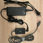
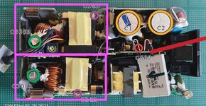
PB 5xx original AC adapter re-cap & modern replacement

I had thought about that actually earlier today. Would be neat if I could integrate an automatic voltage switch or something inside of each tip instead of relying on a dial that I'd have to set each time, would kill two birds with one strong. So yeah that may be the way to go. I'd just have to find a high quality self-contained step down converter for each voltage, seems doable.

What's really annoying about the 3-pin Dells is that halfway through their use of them they switched the key of the tip and the voltage. The XPi and LM series used a 16v with the different keying IIRC, and starting with the CP/C series and associated Inspirons is when they switched to 19/20V and the more common keying. I've seen plenty of cheap untested Latitude XPis and LMs on eBay that I'd loved to have bought to mess with but I've yet to find one of the earlier chargers. You can pretty easily modify a later C-series charger to fit in the earlier ones, but the voltage is trickier.
If you put all the voltage regulators in one box you could use a different size barrel jack for each voltage. Then you wouldn't have to worry about voltage switching and it would be impossible to accidentally connect a laptop to the wrong voltage.

I found out female Dupont wires like they use for gpio on raspberry pis fit tightly over the pins on those 3 pin dells and 4 pin IBM's. You can attach the other ends to a barrel jack and use a 16v ibm or whatever adapter to power it. I had to do that to test a Thinkpad 760cd. It's not ideal but it works for testing. For permanent use you could cut the cord off the more common 20v 3 pin adapter, solder it to a barrel jack and use a 16v brick to power it.
 

Iesca

Well-known member
I had attempted to repair the PSU for my 540c some time ago. Unfortnately, despite replacing the caps, I was unsuccessful, so I ended up just buying a second one. Should that one go too, I will attempt it again; I also have replacement fuses for the thing. Boy is it tight in there!
 

3lectr1cPPC

Well-known member
I found out female Dupont wires like they use for gpio on raspberry pis fit tightly over the pins on those 3 pin dells and 4 pin IBM's. You can attach the other ends to a barrel jack and use a 16v ibm or whatever adapter to power it.
That is GREAT, thanks. I think I'm going to be doing a lot of fun experimenting at some point soon-ish here. And yeah the barrel jack would work great as the intermediary. I'll just find whatever size all the IBMs and other brands used. You know, that "one size" that a bunch of them used. Then use that.
I don't get why they used a 3-pin anyway, one is NC right? You have + and - (ground) to my understanding then the third just... isn't used. Same with "GROUND SENSE" on the 5xx charger.
 
I'll just find whatever size all the IBMs and other brands used. You know, that "one size" that a bunch of them used. Then use that.
The most common size was and probably still is 5.5 x 2.5mm. 5.5mm shell and 2.5mm pin. Make sure you get the heavy duty jacks, the standard cheapo kind is a bit flimsy for the 3+ amps a large laptop can draw. I usually take mine out of dead laptops because they're high quality and free. Also if you have heat shrink tubing that won't quite fit over the jack you can stretch it a bit with a pair of needle nose pliers.
I don't get why they used a 3-pin anyway, one is NC right? You have + and - (ground) to my understanding then the third just... isn't used. Same with "GROUND SENSE" on the 5xx charger.
Probably to force you to buy their charger instead of using a 3rd party one. They could have also intended to do something like the separate battery charging circuit on the PowerBook 500 series. I don't know why they did that either. Both vbatt and vmain are 16v. Either way I'd do some probing and make sure the 3rd pin doesn't do something.

Some of those 3 pin dells also had the power jack in the middle of the right side of the laptop which is the stupidest location I've ever personally seen for a power jack.
 

3lectr1cPPC

Well-known member
One of these would probably work well. Pulled from a dead T21 thinkpad and already has wires soldered, though they’re in parallel for whatever reason? Could probably still use it by soldering both together for + and -.
I’ve got two of them as well, and even better, I would be able to use a standard IBM supply with 16v with no modifications to power my 500 series laptops. I may just do that as well tomorrow, seems like a no-brainer. Great idea on just using the jack from a different laptop.
8BFE16D1-A76A-42C5-A869-2610E9556C5D.jpeg
 
One of these would probably work well. Pulled from a dead T21 thinkpad and already has wires soldered, though they’re in parallel for whatever reason? Could probably still use it by soldering both together for + and -.
I’ve got two of them as well, and even better, I would be able to use a standard IBM supply with 16v with no modifications to power my 500 series laptops. I may just do that as well tomorrow, seems like a no-brainer. Great idea on just using the jack from a different laptop.
View attachment 59531
That is exactly the jack I used for my 500 series adapter. Also pulled from a dead T20 series. I trimmed down the plastic and filed the corners so I was able to stretch out 3/8 inch heat shrink tubing to fit over it. I put 2 zip ties on the cord to give the large heat shrink something to grab onto because the cord isn't very thick. I also unsoldered the ibm wiring and soldered the 520 charger wires directly to the jack. The shield should be tied to ground, I reshaped and trimmed down the little spring clip on the bottom and soldered it to that because it's tied to ground.

The nice thing about the ibm jack with its factory wiring is if you get male to female Dupont wires the male end is a force fit into the ibm wiring plug. So the adapter from ibm barrel jack to Dell 3 pin or ibm 4 pin could be solder free.

The wires on the ibm jack are doubled for extra current capacity. I'm not sure if the T20 series actually needed it or if it was for safety margin but I only used 2 wires for testing the 760cd which had a 133 mhz pentium and originally came with a 2.2 amp charger. The average Dupont jumper wire is 24 gauge so keep the current draw realistic, 1.5-2 amps and keep them short. The pentium 3 ThinkPads came with 4.5 amp chargers. I'm not sure how much they actually draw but even without a battery something like that is probably to much. If you can find quality Dupont wires with legit 20 or 22 gauge wire they'd probably be better. But I'd still only use it for short rounds of testing to prove that the laptop works before building a real power cable.
 

Iesca

Well-known member
Regarding pins on the 5xx PSU, one of the pins is specifically for charging the battery, correct? Obviously if the batteries are dead, no need to have that one connected at all going forward.
 
Regarding pins on the 5xx PSU, one of the pins is specifically for charging the battery, correct? Obviously if the batteries are dead, no need to have that one connected at all going forward.
Yes. There is a diagram in an earlier post. I think you should be able to leave the vbatt wire disconnected. Just cover the wire with heat shrink or something so it doesn't short out.

On my adapter I hooked vbatt and vmain together and soldered them to 16v on the barrel jack. I don't have a battery to see if it still charges but the laptop itself is working normally.
 

Fizzbinn

Well-known member
Crazy question... the vbatt and vmain are looking to be able to draw 2A at 16v. If *someone* were to use a modern 4.5A 16v power supply why couldn't you just tie vbatt and vmain in together to the modern power supply?
 

Fizzbinn

Well-known member
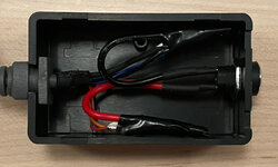
Here's what mine looks like:

IMG_4289.jpeg

IMG_4290.jpeg

I don't have a working battery so don't know if it would run and charge at the same time but it works just fine with vbatt and vmain tied together and no battery installed...
 
Last edited:

3lectr1cPPC

Well-known member
Very clean work! I know mine won't end up looking that good. It is probably a good idea to desolder the wires straight from the PSU board instead of just chopping the connector off. At the same time I'm not looking forward to desoldering the vertical board they're attached to in the 5xx PSU.
 
Here's what mine looks like:

View attachment 59571

I don't have a working battery so don't know if it would run and charge at the same time but it works just fine with vbatt and vmain tied together and no battery installed...
What kind of box is that. That's an amazingly clean job.

I also don't have a working battery to see if it still charges. I don't know if there's a legitimate reason why apple separated them or if it was just cheaper to build the power supply as 2x 2amp vs 1x 4amp at that time.
 

Fizzbinn

Well-known member
I have two dead 5xx power supplies in good physical condition, one even cracked open (hand squeeze pressure) with basically no damage. However when I got another PB 540 its power supply had a case basically destroyed on one end. I didn't feel too bad cannibalizing it to make the above.

I don't recall it being too hard to desolder the PS cable connections from the 5xx PSU board, solderwick is good stuff.

@mustagcoupe - Parts I used:
If I had more 5xx PS cables I could make more since I got more cases and jack sockets then I need but just the one works for my purposes and I'm still holding out that I will try to restore the other two I have. (although my confidence in that is lowered by recent posts on this thread...)
 
Last edited:

3lectr1cPPC

Well-known member
I've got one of those proper Hakko solder sucker machines so I know I can get the parts out no trouble, but still can be stubborn nonetheless. I'll get it I'm sure. Tomorrow we'll see. Today was a busy day in other ways.
 

MacUp72

Well-known member
that connecting box looks good, well done..that way you dont have to butcher the IBM brick and still can use it together with the PB.
But as said, it wont charge the batteries as only one 16V rail is in there..and you said you have two working ones?
parallel I would try to repair your second original one.
 
But as said, it wont charge the batteries as only one 16V rail is in there.

Fizzbinn and I both connected vbatt and vmain to 16v so the battery charging circuit has power. But neither one of us has a working battery so see if it will charge with vbatt and vmain tied together. It's unclear if the battery charging circuit actually has to be separated to charge or if apple just found it cheaper to design a power supply that supplied 2x 2amp vs 1x 4amp. Either way working PowerBook 500 series batteries are very uncommon and it's very unlikely that my 520c will ever see another battery so it doesn't really matter if the battery charges or not.
 

3lectr1cPPC

Well-known member
Once I get a spot welder to rebuild my 500 series batteries I can test this out. Both my battery packs have already been disassembled and with parts I have now, I can build one working battery out of the two. Second one too if I can source a replacement fuse, the leaking cells ate one of the two fuses.
 

MacUp72

Well-known member
Fizzbinn and I both connected vbatt and vmain to 16v so the battery charging circuit has power. But neither one of us has a working battery so see if it will charge with vbatt and vmain tied together. ..
the original circuit has two separate 16V rails, one for main power and one for charging the battery.

z.jpg
 
the original circuit has two separate 16V rails, one for main power and one for charging the battery.
Yes but it's unclear why it is like that. Do they actually need to be separate 16v rails or did apple just design the power supply with 2 separate 2amp 16v rails because it was cheaper and easier than building 1x 4 amp at the time. None of us has a working battery to see how it charges with vbatt and vmain tied together to the same 16v source. But without a battery the computer operates normally with vbatt and vmain connected together.
 
Top