Fizzbinn
Well-known member
*** Originally posted 4/11/2021, reposting due to outage. Thankfully the text was in Google Cache. ***
I finally got around to re-capping the TDK power supplies in my two original LC's, LC III and Quadra 605. There is a bunch of info in different threads and on other sites but thought others might find this summary useful.
My two original LC's had non-working TDK power supplies labeled:
TDK Model Number: 699-0153
Apple Part Number: 699-0153
+5V 3.25A
-5V 0.075A
+12V 0.75A
My LC III and Quadra 605 had working TDK power supplies labeled:
TDK Model Number: 614-0003
Apple Part Number: 614-0003
+5V 3.75A
-5V 0.075A
+12V 0.78A
I had expected it was likely there might be noticeable differences in general and/or with the capacitors I'd find inside but turns out they are identical from a capacitor prospective and while I didn't go over/compare every component I didn't observe any obvious, noticeable differences.
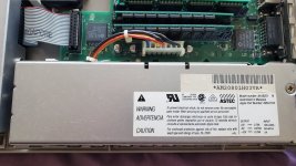
699-0153 (LC):
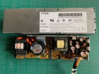
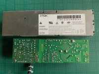
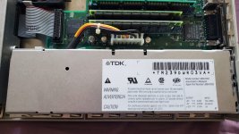
614-0003 (LC III & Quadra 605):
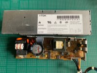
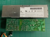
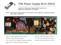
Capacitor List:
C3 - 180µf | 385WV d:30mm h:25mm
C8 - 8.2µf | 50V d:5mm h:8mm
C51, C52, C55 - 1000µf | 10V d:10mm h:20mm
C53, C54 - 270µf | 25V d:8mm h:20mm
C56 - 56µf | 25V d:6mm h:12mm
C60 - 47µf | 25V d:6mm h:12mm
C64 - 270µf | 10V d:6mm h:15mm
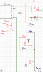
Capacitor Diagram:
I ordered the following replacement electrolytic capacitors from Mouser:
C51, C52, C55 - 1000µf | 10V d:10mm h:20mm
647-UPW1A102MPD
C53, C54 - 270µf | 25V d:8mm h:20mm
647-UPJ1E271MPD
C56 - 56µf | 25V d:6mm h:12mm
647-UPM1E560MED
C60 - 47µf | 25V d:6mm h:12mm
647-UPV1E470MGD
C64 - 270µf | 10V d:6mm h:15mm
647-UPJ1A271MED
...And the results:
LC PS #1: 5V works now, however 12V is reading only 2V...
LC PS #2: Now Works!
LCIII PS: Still Works!
Quadra 605 PS: Still Works!
Overall I'm pretty happy, the 699-0153 (LC) PS's had clear leakage, especially bad on the C53, C54 -270µf 25V capacitors. Even though they both worked before, the 614-0003 (LC III & Quadra 605) power supplies' C56 - 56µf 25V and C60 - 47µf 25V capacitors had some leakage. Hopefully these will last a good while longer now!
I need to dig into LC PS #1, anyone have any thoughts on what might cause 12V to only measure 2V?
I finally got around to re-capping the TDK power supplies in my two original LC's, LC III and Quadra 605. There is a bunch of info in different threads and on other sites but thought others might find this summary useful.
My two original LC's had non-working TDK power supplies labeled:
TDK Model Number: 699-0153
Apple Part Number: 699-0153
+5V 3.25A
-5V 0.075A
+12V 0.75A
My LC III and Quadra 605 had working TDK power supplies labeled:
TDK Model Number: 614-0003
Apple Part Number: 614-0003
+5V 3.75A
-5V 0.075A
+12V 0.78A
I had expected it was likely there might be noticeable differences in general and/or with the capacitors I'd find inside but turns out they are identical from a capacitor prospective and while I didn't go over/compare every component I didn't observe any obvious, noticeable differences.
699-0153 (LC):


614-0003 (LC III & Quadra 605):


Capacitor List:
C3 - 180µf | 385WV d:30mm h:25mm
C8 - 8.2µf | 50V d:5mm h:8mm
C51, C52, C55 - 1000µf | 10V d:10mm h:20mm
C53, C54 - 270µf | 25V d:8mm h:20mm
C56 - 56µf | 25V d:6mm h:12mm
C60 - 47µf | 25V d:6mm h:12mm
C64 - 270µf | 10V d:6mm h:15mm
Capacitor Diagram:

Notes:
Other sites have noted that on the AC side of the board C5 and C8 likely don't need to be replaced. I generally like to replace them all just to be sure but couldn't find Nichicon caps to match on Mouser and decided to leave the originals for now.
I ordered the following replacement electrolytic capacitors from Mouser:
C51, C52, C55 - 1000µf | 10V d:10mm h:20mm
647-UPW1A102MPD
C53, C54 - 270µf | 25V d:8mm h:20mm
647-UPJ1E271MPD
C56 - 56µf | 25V d:6mm h:12mm
647-UPM1E560MED
C60 - 47µf | 25V d:6mm h:12mm
647-UPV1E470MGD
C64 - 270µf | 10V d:6mm h:15mm
647-UPJ1A271MED
...And the results:
LC PS #1: 5V works now, however 12V is reading only 2V...
LC PS #2: Now Works!
LCIII PS: Still Works!
Quadra 605 PS: Still Works!
Overall I'm pretty happy, the 699-0153 (LC) PS's had clear leakage, especially bad on the C53, C54 -270µf 25V capacitors. Even though they both worked before, the 614-0003 (LC III & Quadra 605) power supplies' C56 - 56µf 25V and C60 - 47µf 25V capacitors had some leakage. Hopefully these will last a good while longer now!
I need to dig into LC PS #1, anyone have any thoughts on what might cause 12V to only measure 2V?

