LC TDK 699-0153 PSU Reference

lostone

Member
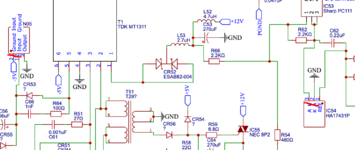
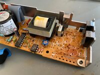
Can anyone confirm the transformer outputs are basically just two at 5V each? I've done everything except start feeding the inputs to confirm and all I find appears to be two coils or one coil with wired to 5 pins. I wasn't able to see how the voltage feeding the 5V line is negative since pin3 is ground, and pins 1 and 5 seem to be tied to pin 3. Pins 2 and 4 appear to be tied together (the other end of 5V chage). What I called output pin 1 could be 5 and is tied to the regulator though a diode w/2V drop. So while the voltage on that pin relative to ground was 5V I'm confused. But I didn't spend much time thinking that through. I also don't know if there's one or two coils wrapped opposite or one coil with multiple output pins. I also know nothing anything about the input/output relationship without testing. I removed the transformer from this TDK supply so I can test that out at some point.

The Astec 16251 also has a 78N05 regulator but it's an AN78N05 not C78N05 and without sheets, can only assume they should be similar.
I found these voltages on pins:
pin1: gnd
pin2: -6.3V (input)
pin3: -5V
While these are two different circuits, and I don't know if the C78N05 and the AN78N05 are pin compatible, this does suggest the input on the TDK should be -6.3V and the labels/pins in the schematic may be correct. This isn't fun any more. LOL
 

cesare

Member
Just to say thanks for this schematic - i've been working on a temperamental LC power supply, which was sometimes working with somewhat out of spec voltages, sometimes hiccuping, and sometimes not even starting. It had previously suffered from capacitor leakage, and had various components with black corroded legs, and it was pretty tricky to measure stuff except from below, and this helped me locate the parts and check stuff out.

Nothing seemed out of order, so I gave it an extra serious clean (Amberclens to the rescue) and let it dry out for a few days, and it's been good ever since, so likely to have been electrolyte causing spurious conductive paths somewhere on the low voltage side. One more LC saved...
 

ben68k

Member
@ben68k since you're actively digging around in the circuit, could you do me a favor and check the voltages on the C78N05 (IC51). I can't figure out the input voltage (pin1), (with pins numbers 1, 2. 3 when looking at the label side). As noted a couple posts early I am unsure questions about the schematic labels/signals and my -5V is totally unstable and trying to figure out if that's regulating correctly. When I test with a DC supply as a negative regulator my output varies with the input voltage and I thought that should be constant over a wide input voltage range. Thanks if you can.
Hi,

Sorry - I just saw this. Only today did the forum email me that there was a reply (shrug).

I will try to get this info to you as soon as I can.

ben
 

lostone

Member
Hi,

Sorry - I just saw this. Only today did the forum email me that there was a reply (shrug).

I will try to get this info to you as soon as I can.

ben
Thanks, I had recently picked up some 7805s to compare against what's in the board and the 75C05 does appear to be the standard positive 5V part, so installing found I didn't have an LC board nearby so checked it unloaded and found -5V was still all over, the other voltages did what I'd expect. I'm expecting there's an input voltage greater than 7V, but in it's reversed. So to see -5 label output on pin 6 of the transformer seems like that should read 5V and more like 6V or 7V.

I also removed many parts to test and still haven't found anything strange, but I also don't know exactly what the main transformer output on pin10 and 11 (hope I remember the right #s).

I have questions about R56 (the blue pot next to transformer) it's around 780ohm from 2 to 3 but since 5V looks stable I'm guessing it's set correctly.

I plan on grabbing a LC board from storage this weekend and will continue to keep poking at it. I look forward to your findings.
 

lostone

Member
Welp, I guess replacing the C78N05 with an ST L78M05ABV fixed the problem, this is what now see:
TDK Supply replacing C78N05 with ST L78M05ABV.PNG


Here's my minor contribution to this thread which I found really useful! Thanks to @SuperSVGA!
Here's two corrections to the schematic. As discussed previously, the pin numbers for IC51 (C78N05) were incorrect. The labels are correct for the pin numbers which were flipped. Also found pin labels for the 17431 (IC54) has labels swapped for pins 2 and 3.

TDK Schematic corrections.PNG

I'm also kinda confused by wiring for the 7805 instead of a 7905 but I guess it's fine because this basically just moves ground 5V lower and the output being 5V higher at ground internally it's doing its job. I expect I'll never find a use for that trick!
 

ben68k

Member
HI,

Looks like you got things going. Thats great !

When I get some info, I can still post it just in case anyone else needs it. I have about 23 of these supplies I am working on right now. The first one I did is where I really learned about them in detail. It had really bad cap leakage (you can see from the photo - and that was after the board was cleaned). I ended up removing every single component from the board to clean it so i measured and tested every single component individually. Except for the caps of course they all tested good surprisingly. Except I think I let the smoke out of the -5 v reg myself when testing it so I had to track some down and order a replacement - oops. But all good now. Because switching power supplies require a load (if not a good built in one) I just made a simple test load since I actually don't own an LC. Really just a few power resistors is all you need.

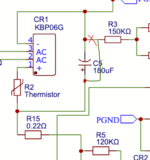
For your updated schematic, can you verify the placement of R3 in relation to C5? I am pretty sure that R3 should be shown on the schematic to connect to the positive side of C5 where you have it shown to connect to the negative side.

The blue pot is used to adjust the feedback voltage from the output side back to the input side. Once I get everything working, I load the supply and monitor the output voltages (with a good meter, btw, not just the ones on my test load). Then I tweak the pot to dial in the voltages. The -5 is fixed and does not change. The 5 and 12 change together. I have been aiming for arount 4.9 to 5.05 or so on the 5 and then whatever the 12 ends up at is where it stays - usually around 11.8. The challenge here is that without official documents/schematics by the manufacturer, i don't know what the accepted tolerance is so I am just going with 5 and 11.8. If anyone has the LC schematics etc perhaps they could identify what the LC input tolerance for voltage is and let us know.

Just disclaimer - as far as switching power supplies go, I am not an expert (although I am quickly becoming a self taught one ha ha)
So any input/corrections from others is greatly appreciated and I am happy to provide whatever info I can to help others keep these things running.

There are other (probably cheaper with very little time labor) ways to power an LC (ie. you could use a variety of modern switching power supplies and connector adaptors etc and probably even fit them inside the case of the tdk as a replacement) But that is not the point for me. I want to try and keep as much old school original running as I can. The work, time, and journey is where you find the growth and enjoyment.

Ben


IMG_7615.jpeg IMG_8664.jpeg
 

lostone

Member
For your updated schematic, can you verify the placement of R3 in relation to C5? I am pretty sure that R3 should be shown on the schematic to connect to the positive side of C5 where you have it shown to connect to the negative side.

My supply is fully assembled, and the original work is not mine so I can't make any corrections.
But I can say R2, R3, and R15 are all connected to the same high side of C5 (the rectified input voltage from CR1).
1717955069395.png

For the output voltages the negative is the result of the positive 5V regulator (C78N05) wired so the 5V output is below ground rather than above.
For the 12V and 5V they a controlled by IC54 (both the parts I provided corrections for above, I wonder why.... lol) IC54 is configured to output 12V and 5V comes from the divider with the 2K pot.

Standard tolerances are close to +/-10% but I'd go right around the mean values shown in my scope shot.
5V around 5.1-5.2 even slightly higher is fine.
12V should be 12.2-12.4 and changing that isn't as easy as adjusting a pot... so you don't.
-5V is fixed with the regulator output.

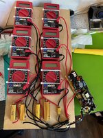
Looks like you got a cart full of meters from HF, I like it!

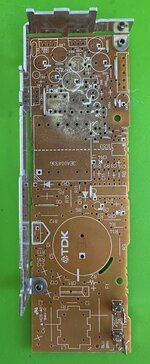
Oh and that discoloration on the boards, that's not from leakage I'm pretty sure it's called crazing and the result of the board not having a mask on the topside. Good caps, as you found, have their electrolyte and haven't leaked. One that leak/dry out will lose capacitance.
 

ben68k

Member
Can anyone confirm the transformer outputs are basically just two at 5V each? I've done everything except start feeding the inputs to confirm and all I find appears to be two coils or one coil with wired to 5 pins. I wasn't able to see how the voltage feeding the 5V line is negative since pin3 is ground, and pins 1 and 5 seem to be tied to pin 3. Pins 2 and 4 appear to be tied together (the other end of 5V chage). What I called output pin 1 could be 5 and is tied to the regulator though a diode w/2V drop. So while the voltage on that pin relative to ground was 5V I'm confused. But I didn't spend much time thinking that through. I also don't know if there's one or two coils wrapped opposite or one coil with multiple output pins. I also know nothing anything about the input/output relationship without testing. I removed the transformer from this TDK supply so I can test that out at some point.

The Astec 16251 also has a 78N05 regulator but it's an AN78N05 not C78N05 and without sheets, can only assume they should be similar.
I found these voltages on pins:
pin1: gnd
pin2: -6.3V (input)
pin3: -5V
While these are two different circuits, and I don't know if the C78N05 and the AN78N05 are pin compatible, this does suggest the input on the TDK should be -6.3V and the labels/pins in the schematic may be correct. This isn't fun any more. LOL
Hello,

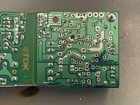
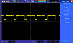
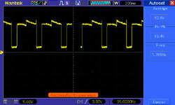
Attached image is looking at the underside of the board (the solder side) with the input on the left and output on the right.
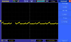
Measuring the output of the transformer is a bit tricky because it will be "pulsing".
And I would imagine that the frequency and hence voltage would be a bit different depending on load and feedback circuit and adjustment and what not.

Ben


Screenshot 2024-06-09 at 2.51.44 PM.png
 

ben68k

Member
My supply is fully assembled, and the original work is not mine so I can't make any corrections.
But I can say R2, R3, and R15 are all connected to the same high side of C5 (the rectified input voltage from CR1).
View attachment 74613

For the output voltages the negative is the result of the positive 5V regulator (C78N05) wired so the 5V output is below ground rather than above.
For the 12V and 5V they a controlled by IC54 (both the parts I provided corrections for above, I wonder why.... lol) IC54 is configured to output 12V and 5V comes from the divider with the 2K pot.

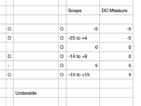
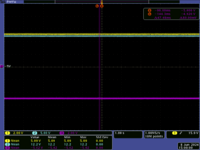
Standard tolerances are close to +/-10% but I'd go right around the mean values shown in my scope shot.
5V around 5.1-5.2 even slightly higher is fine.
12V should be 12.2-12.4 and changing that isn't as easy as adjusting a pot... so you don't.
-5V is fixed with the regulator output.

Looks like you got a cart full of meters from HF, I like it!

Oh and that discoloration on the boards, that's not from leakage I'm pretty sure it's called crazing and the result of the board not having a mask on the topside. Good caps, as you found, have their electrolyte and haven't leaked. One that leak/dry out will lose capacitance.

That line you drew on the schematic looks exactly like the one I drew on my printed copy here too lol

Ya, HF meters. And I tell you what - what a disaster. Obviously I didn't expect them to be super accurate; I just want to make sure current is flowing and a general idea of the voltage/current on the rails all at once. You would think they could handle that. And they do - sometimes. I have been pulling my hair out with these supplies because sometimes they seem to work and sometimes they don't and sometimes the voltages are 1/2 what they should be and sometimes........ what the heck is wrong with these supplies?!?!?! turns out - a lot of the time it is the stupid HF meters!! Sometimes they just randomly read at 1/2 the expected voltage, and sometimes they just randomly stop passing current altogether (thereby removing the load from the supply) and causing shutdown, sometimes one will just go zero, sometimes..... Anyway - let that be a learning lesson for everyone, make sure you don't blindly trust that your meters are working.

What load were you at when you took your output voltage scope shot with 5.09v and 12.2v ?
Was that with an actual LC or a simulated load? What current draw? I set my test load to run around 1a and 0.25a. (haven't done extensive testing yet, but...) so far what I have seen is that if I push closer to the supply's rated load, it seem to not really be able to handle it very well. I would be curious to know what the typical current draw from an actual LC would be.

Thank you

Ben
 

lostone

Member
That line you drew on the schematic looks exactly like the one I drew on my printed copy here too lol

Ya, HF meters. And I tell you what - what a disaster. Obviously I didn't expect them to be super accurate; I just want to make sure current is flowing and a general idea of the voltage/current on the rails all at once. You would think they could handle that. And they do - sometimes. I have been pulling my hair out with these supplies because sometimes they seem to work and sometimes they don't and sometimes the voltages are 1/2 what they should be and sometimes........ what the heck is wrong with these supplies?!?!?! turns out - a lot of the time it is the stupid HF meters!! Sometimes they just randomly read at 1/2 the expected voltage, and sometimes they just randomly stop passing current altogether (thereby removing the load from the supply) and causing shutdown, sometimes one will just go zero, sometimes..... Anyway - let that be a learning lesson for everyone, make sure you don't blindly trust that your meters are working.

What load were you at when you took your output voltage scope shot with 5.09v and 12.2v ?
Was that with an actual LC or a simulated load? What current draw? I set my test load to run around 1a and 0.25a. (haven't done extensive testing yet, but...) so far what I have seen is that if I push closer to the supply's rated load, it seem to not really be able to handle it very well. I would be curious to know what the typical current draw from an actual LC would be.

Thank you

Ben
Well then nice job on your schematic update! I hope those can get rolled in to the published one.

The values I see are on an LC, my HD wasn't always starting up right so those may have been with power to the drive disconnected but I believe it was connected. Those voltages also look in line with the ASTEC version of this supply and other Apple II supplies I've worked on (everything after the original II supply regulate fairly well unloaded which is good for a quick power on test). The only voltage which I've seen consistently low (or is it high?) is -12V which runs around -11.8 but that voltage isn't on the macs! 0.2V below is perfectly good, +/- 5% tolerance on any voltage would be the sweet spot.

Interesting findings on the HF meters, I got one (it was free so why not) but that was defective and they wouldn't swap it; I can't really blame them for that. I did buy another for like $2 and I found it worked surprising well. Not fast but fairly accurate, and I think it's the one I dragged to the lab every day in college. They were quite popular with the electrical engineering faculity and students for anything that didn't need high precision. Was pefect student budget meter! I don't know that I ever used it for current, I thought it had a surprisingly high 5A current. I just checked your photo again and noticed that all appear to be set the same way even though wired different on each side. Then noticed the 20VDC is 180degrees from 5A mode lol, that's gotta be confusing if you miss the very subtile tapered end indicator. I'm sure I'd mark it up with something I could easily notice before banging my head on that wall too many times!
 

dougg3

Well-known member
I just wanted to say thanks for this awesome thread and the very useful pictures! I recently bought a Mac LC with a TDK 699-0153 PSU. The logic board caps had leaked, but that repair was straightforward. The PSU gave me fits though. The capacitors on the low voltage side of the board had leaked extremely badly, especially the ones that weren't Nichicon originally. The bottom of the PCB was black underneath them.

After removing all the caps on that side of the board, cleaning everything I could with isopropyl alcohol, and then reinstalling replacements, it still didn't work. The -5V rail was fine, but the 5V and 12V rails were producing voltages that were too low. I didn't write the exact voltages down but they were way too low. Something like 4.4 volts and 11 volts.

I noticed that the solder joints on the nearby components looked really dull and ugly, so I reflowed them with fresh solder, and that improved things a little bit. The 5V rail's voltage went up a little (still too low though -- it would just chime repeatedly when I powered it on).

The leakage had been really really bad, so I decided to take drastic measures and depopulate almost everything on that side of the board. This ended up being a smart move because there was still leaked cap goo all over the place under nearby components. Here you can see all the extra gunk that I missed the first time.

IMG_3574.jpeg

Removing everything allowed me to thoroughly clean the board as well as each individual component. Plus it gave me a chance to pull out all of the original solder that had clearly been contaminated by the electrolyte. I put each part into its own individual labeled tiny bag so that I knew which one was which.

I also noticed a few places on the copper where there was dark staining from the leakage under the solder mask, so I scraped the copper until it was gone and then covered everything back up with some UV solder mask. It looks a little messy, but hey, it does the job. Here's the solder mask repair before I started replacing everything. There might be a few ugly solder whiskers here and there that I fixed before putting it all back together.

IMG_3604.jpeg

After soldering everything back into place, now it's great. Without the original hard drive plugged in, I get 5.1V, 11.92V, and -5.04V. With the hard drive plugged in, the 12V rail dips down a bit to 11.76V but it still seems to work fine. I'm definitely happy!

TL;DR: if the caps have leaked enough, you really need to clean everywhere in the vicinity. Not just underneath where the capacitors were.
 
Top