SuperSVGA
Well-known member
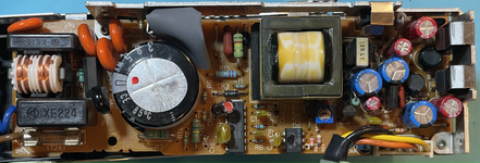
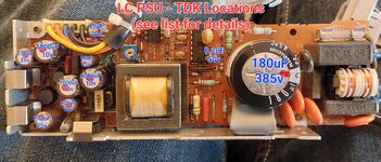
LC TDK 699-0153 PSU
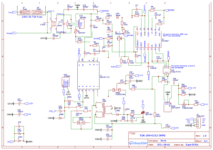
Since there doesn't seem to be a lot of information on these LC power supplies, I thought I would share what I've been working on the past few months.My next goal is figuring out what everything on the board does in order to ease diagnosis, unfortunately I don't know much about SMPS or EE in general, so if anyone has any insights feel free to share. I vaguely understand what's going on but not enough to determine how specific voltages are sourced.
Also if anyone can determine the specs of the two transformers, let me know.
Board Components
All the components on the board, with whatever specs I could determine. I wasn't able to identify most of the diodes.Capacitors |
|---|
Loc | Capacitance | Voltage | Type | Temp | Lead | Height | Diameter |
|---|---|---|---|---|---|---|---|
| C1 | 0.22uF | 250V | X1 Safety | 23.5mm | 19.7mm | 24.9mm | |
| C2 | 0.1uF | 250V | X1 Safety | 22.9mm | 16mm | 24.6mm | |
| C3 | 3.3nF | 400V | Ceramic Safety | 7.2mm | 14.7mm | 13.4mm | |
| C4 | 3.3nF | 400V | Ceramic Safety | 7.2mm | 14.7mm | 13.4mm | |
| C5 | 180uF | 385V | Electrolytic | 85°C | 10.5mm | 25mm | 30mm |
| C6 | 0.01uF | 630V | Metal Film | 12mm | |||
| C8 | 8.2uF | 50V | Electrolytic | 105°C | 5.15mm | 10.8mm | 5.25mm |
| C9 | 0.001uF | Polyester Film | 4.5mm | ||||
| C10 | 0.047uF | 50V | Polyester Film | 6.7mm | |||
| C11 | 3.3nF | Polyester Film | 4.5mm | ||||
| C12 | 3.3nF | 400V | Ceramic Safety | 7.2mm | 14.7mm | 13.4mm | |
| C13 | 3.3nF | 400V | Ceramic Safety | 7.2mm | 14.7mm | 13.4mm | |
| C14 | 0.01uF | Polyester Film | 6mm | 5mm | |||
| C51 | 1000uF | 10V | Electrolytic | 105°C | 5.25mm | 21.9mm | 10mm |
| C52 | 1000uF | 10V | Electrolytic | 105°C | 5.25mm | 21.9mm | 10mm |
| C53 | 270uF | 25V | Electrolytic | 105°C | 3.8mm | 19.9mm | 8mm |
| C54 | 270uF | 25V | Electrolytic | 105°C | 3.8mm | 19.9mm | 8mm |
| C55 | 1000uF | 10V | Electrolytic | 105°C | 5.25mm | 21.9mm | 10mm |
| C56 | 56uF | 25V | Electrolytic | 3mm | 4.8mm | ||
| C57 | 0.1uF | 63V | Metal Film | ||||
| C60 | 47uF | 25V | Electrolytic | 105°C | 4.7mm | ||
| C61 | 0.001uF | 250V | Polyester Film | ||||
| C62 | 0.22uF | 63V | Metal Film | 8.7mm | |||
| C64 | 270uF | 10V | Electrolytic | ||||
| C66 | 0.001uF | 250V | Polyester Film |
Resistors |
|---|
Loc | Resistance | Power | Tolerance |
|---|---|---|---|
| R1 | 1MΩ | 1/4W (250mW) | ±5% |
| R3 | 150KΩ | 1/2W (500mW) | ±5% |
| R4 | 150KΩ | 1/2W (500mW) | ±5% |
| R5 | 120KΩ | 1/2W (500mW) | ±5% |
| R6 | 39Ω | 1/8W (125mW) | ±5% |
| R7 | 120KΩ | 1/8W (125mW) | ±5% |
| R8 | 13KΩ | 1/8W (125mW) | ±1% |
| R9 | 5.6KΩ | 1/8W (125mW) | ±1% |
| R10 | 260Ω | 1/8W (125mW) | ±5% |
| R11 | 120Ω | 1/8W (125mW) | ±5% |
| R12 | 0.22Ω | 1/2W (500mW) | ±5% |
| R13 | 120Ω | 1/8W (125mW) | ±5% |
| R14 | 150KΩ | 1/8W (125mW) | ±5% |
| R15 | 0.22Ω | 1/2W (500mW) | ±5% |
| R16 | 10KΩ | 1/8W (125mW) | ±5% |
| R51 | 27Ω | 1/2W (500mW) | ±5% |
| R54 | 460Ω | 1/8W (125mW) | ±5% |
| R57 | 10KΩ | 1/8W (125mW) | ±5% |
| R58 | 22Ω | 1/8W (125mW) | ±5% |
| R59 | 6.8Ω | 1/8W (125mW) | ±5% |
| R61 | 12KΩ | 1/8W (125mW) | ±1% |
| R62 | 2.2KΩ | 1/8W (125mW) | ±5% |
| R63 | 220KΩ | 1/4W (250mW) | ±5% |
| R64 | 100Ω | 1/4W (250mW) | ±5% |
| R66 | 2.2KΩ | 1/8W (125mW) | ±5% |
Diodes |
|---|
Loc | Identifier | Type |
|---|---|---|
| CR1 | KBP06M 3N250 | Bridge Rectifier |
| CR2 | ||
| CR3 | 2 2G 1DF | |
| CR4 | 24B | Zener |
| CR5 | 62B | Zener |
| CR51 | C82M | Barrier Diode |
| CR52 | B82M | Barrier Diode |
| CR53 | 2 2G 1DF | |
| CR54 | Zener | |
| CR55 | Zener | |
| CR56 | Zener | |
| CR57 | 2 2G 1DF |
Other Components |
|---|
Loc | Name | Identifier |
|---|---|---|
| F1 | 2A 250V T2A | |
| IC1 | Power IC | M51996P |
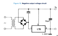
| IC51 | Voltage Regulator | C78N05 |
| IC53 | Optocoupler | Sharp PC111 |
| IC54 | Shunt Regulator | HA17431P |
| IC55 | Thyristor | NEC 8P2 |
| L1 | Power Choke? | 290A P27 |
| L51 | Inductor - 2.2uH | 2R2M |
| L52 | Inductor - 4.7uH | 4R7M |
| L53 | Inductor - 2.4uH? | |
| Q1 | MOSFET | K1024 |
| R2 | Thermistor | 16D-9 |
| R56 | Potentiometer | 202 |
| T1 | Transformer | TDK MT1311 M92411 |
| T51 | Transformer | T29 MX |
| 24AWG Solid Wire | ||
| 5 Pin LC Power |
Unpopulated Board Photos
Images of the board with all the components removed.Populated Board Photo
A picture of a fully populated board, with replaced secondary capacitors.Redrawn Board Photos
The PCB redrawn, mostly accurate.Gerber files are also attached in the post.


