• Updated 2023-07-12: Hello, Guest! Welcome back, and be sure to check out this follow-up post about our outage a week or so ago.

jmacz Mac IIfx Project

jmacz

Well-known member
Cheap PSUs are typically worse at regulation (ripple), and machines of this vintage are more sensitive to that than modern machines (as they re-regulate most rails anyways). Additionally, that PSU is likely a simple group regulated type which means the voltage output on individual rails are roughly tracked together corresponding to the load on 12v rail. Thus, they rely on a significant 12v load. These machines do not use 12v much, so it is likely that 5v will go out of spec.

Looks like my issue is not with the IIfx PSU so I should be able to continue using the now recapped stock one. But FWIW, I was checking the voltages coming out of the Coolmax I-400 both with my IIfx unloaded (just a video card) and more loaded (two video cards, ethernet card, multiple storage devices, etc) and the 5V seems to be holding relatively well (4.90V to 4.94V).
 

jmacz

Well-known member
Got a chance to look at the IIfx today and there's something strange going in that ADB area.

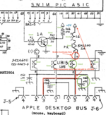
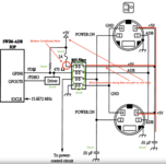
Here are the two diagrams I was able to pull up, one is from Bomarc (the one that @bigmessowires provided earlier) and the second one is from Guide to the Macintosh Family Hardware Second Edition.

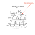
Bomarc:
Screenshot 2023-11-05 at 2.45.55 PM.png

Guide to the Macintosh Family Hardware Second Edition (pg 295):
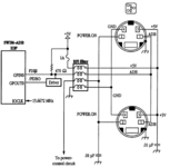

Screenshot 2023-11-05 at 3.15.43 PM.png

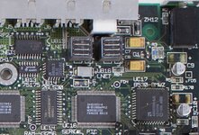
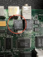
UB15 seems to be an RFI filter and looks like this on the IIfx motherboard:
IMG_5885.JPG

So what is strange... I first measured resistance between the pins of the ADB connector:
  • Data (1) vs VCC (3): resistance around 460 ohms.
  • Data (1) vs Ground (4): resistance around 480 ohms.
  • Data (1) vs PFW (2): floating between 0 ohms and 1.4k ohms.
  • PFW (2) vs VCC (3): floating between 0 ohms and 1.4k ohms.
  • PFW (2) vs Ground (4): floating between 0 ohms and 1.4k ohms.
  • VCC (3) vs Ground (4): resistance 16 ohms and buzzing on continuity check.
That doesn't sound right. I thought it might be a faulty C62 causing a partial short between VCC and ground. But I removed C62 and it checked out fine (10nF capacitor). With the capacitor out, there was still a 16 ohm resistance between the two pads it sits on.

So then I thought perhaps UB15 was bad. I could prove it by removing UB15 from the board and checking it, but I wanted to do some more poking before pulling it off.

I see near 0 resistance across L6 and across F2 and from the outer pin of L6 to the outer pin of F2. I also see near 0 resistance from ADB pin 3 (Vcc) and pins 2 and 7 of UB15 (and near 0 resistance between pins 2 and 7 of UB15). I also see near 0 resistance between motherboard ground and pins 3 and 6 of UB15 (and near 0 resistance between pins 3 and 6 of UB15). But I'm seeing 16 ohms of resistance between pins 2/7 and 3/6 of UB15.

I decided to remove L6 instead. F2 seemed heat sensitive as it's a fuse that looks like two metal plates with something in between so I didn't want to touch it. L6 was a surface mounted inductor and easier to remove with a wick. I figured if I remove L6 and I still see 16 ohms between pins 2/7 and 3/6 of UB15, it shouldn't be a short elsewhere on the board and had to be in or near UB15.

Well it got stranger after that. With L6 off the board, I no longer see a semi-short between pins 2/7 and 3/6 of UB15. There's near infinite resistance. So it looks like UB15 itself is fine. But what the heck?

I tested the two pads that L6 was sitting on. No short. One pad goes to 5V Vcc. The other pad goes to F2 with 0 resistance. The two sides of F2 also have zero resistance. F2 to pin 7 of UB15 which according to the schematic is where it's supposed to go, no continuity. What?!? But then testing pin 2/7 of UB15 to ADB port pin3, near zero resistance. AND somehow ADB port pin3 (Vcc) and pin2/7 of UB15 still have connectivity to 5V Vcc (zero resistance also to the far pad of L6 that ties to 5V Vcc). !?!? AND there

So at this point, what I have so far:

L6 - it tests ok off the board.
C62 - it tests ok off the board.
F2 - with L6 removed, testing it on board is fine and shows proper continuity so it's good.
UB15 - with L6 disconnected, I see no partial shorts between pins so I think it's good.

Also these other components in the vicinity, I didn't remove them from the board, but they seem ok: Q1, R3, R65, R66, C61, and C60.

But:
  • I probably have a short on a trace between F2 and UB15 pin 7.. it looks to be disconnected.
  • I probably have a partial short somewhere between F2 and UB15 giving me 16 ohms of resistance to ground.
  • I have a short somewhere between pin 2 of UB15 and the two ADB port pin 3s that is connecting directly to Vcc.
  • Resistance between the Data line and Vcc or ground seems ok so not sure there's anything wrong there?
I don't physically see anything broken on the surface (top or bottom). But there are a few traces that run under UB15... so I guess I have to take it out and see what's going on underneath it perhaps.
 

dougg3

Well-known member
VCC (3) vs Ground (4): resistance 16 ohms and buzzing on continuity check.

This is normal on classic Macs in general. I get similar results on my Macs of the same era. My brain’s too fried to think about what implications that has on the rest of your research, but I thought I would point that out.
 

jmacz

Well-known member
This is normal on classic Macs in general. I get similar results on my Macs of the same era. My brain’s too fried to think about what implications that has on the rest of your research, but I thought I would point that out.

Huh... ok. Well what I think that means is:
  • I probably have a broken (fixed earlier typo) trace between F2 and UB15 pin 7.. it looks to be disconnected.
  • I probably have a partial short somewhere between F2 and UB15 giving me 16 ohms of resistance to ground. Update: @dougg3 mentioned this might be ok.
  • I have a short somewhere between pin 2 of UB15 and the two ADB port pin 3s that is connecting directly to Vcc.
Without L6 on the board, I don't think I should have connectivity to the L6 pad that connects to 5V, yet I do, even with L6 off the board. That I think means the ADB Vcc is not going through the RFI filter?
 

bigmessowires

Well-known member
I agree with Doug that 16 ohms between VCC and GND sounds normal. You're measuring the equivalent load of the entire computer, through all the chips in parallel.

Some of those other test results seem contradictory. Can you triple-check that there's really no continuity from F2 to pin 7 of UB15? Maybe the pads are just covered in dirt and an oxidation layer, so your meter probes aren't making good contact. Try scraping them shiny clean and measuring again. It seems more likely that the continuity is OK and you're simply having trouble measuring it, than that you have a double problem with a broken trace at F2 and also a short somewhere else between ADB pin 3 and Vcc.


  • Data (1) vs PFW (2): floating between 0 ohms and 1.4k ohms.
  • PFW (2) vs VCC (3): floating between 0 ohms and 1.4k ohms.
  • PFW (2) vs Ground (4): floating between 0 ohms and 1.4k ohms.

It's probably not important, but what do you mean by floating? If you ever measure a steady 0 ohms on those, then something isn't right. It might briefly show 0 ohms due to the action of capacitors elsewhere that get charged up by the current from your meter.

If you're definitely sure there's no continuity from F2 to pin 7 of UB15, that's definitely a problem, and I would try adding a patch wire and then testing if your video sync problem is still there.
 

jmacz

Well-known member
I agree with Doug that 16 ohms between VCC and GND sounds normal. You're measuring the equivalent load of the entire computer, through all the chips in parallel.

Ok, sounds good. I'll stop looking at that one.

Some of those other test results seem contradictory. Can you triple-check that there's really no continuity from F2 to pin 7 of UB15? Maybe the pads are just covered in dirt and an oxidation layer, so your meter probes aren't making good contact.

I just triple checked. Definitely no continuity between F2 and pin 7 of UB15.

I placed both probes on either side of F2 and get continuity. I then lift the probe on F2 that is furthest away from UB15 Pin 7 and then place that probe on UB15 Pin 7 and no continuity. To make sure I got good contact on UB15 Pin 7, I then lifted the remaining probe on F2 and moved it to Vcc ADB J5 Pin 3 and get continuity. I've also scraped, cleaned, deoxit'd those pins just to be sure. No continuity.

And then also triple checked that I have continuity between UB15 Pin 2 or Vcc ADB J5 Pin 3 and the L6 pad that's on the +5V side. And I get continuity even with L6 off the board. So that also sounds problematic?

It's probably not important, but what do you mean by floating? If you ever measure a steady 0 ohms on those, then something isn't right. It might briefly show 0 ohms due to the action of capacitors elsewhere that get charged up by the current from your meter.

If I place a probe for example on ADB J5 Pin 2 (PFW) and the other probe on ADB J5 Pin 4 (Ground), I'm seeing the resistance constantly changing between 0 and ~1.4K ohms, it keeps fluctuating. Note all of this testing is with no power to the motherboard, it's completely disconnected. It's not steady at 0. Ignoring this for now though, I didn't feel like this was important.

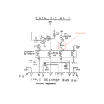
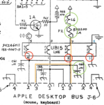
To diagram out what I'm seeing (using both diagrams):

Screenshot 2023-11-05 at 7.58.17 PM.png Screenshot 2023-11-05 at 7.59.44 PM.png

I'm not seeing anything on the surface so I think I need to check under UB15 as it looks like the trace between F2 and pin 7 of UB15 goes underneath it.

If UB15 pin2 and ADB pin 3 have continuity to the far pad (+5V side) of L6, then it's bypassing the RFI filter, correct?
 

bigmessowires

Well-known member
I can't really think of a rational explanation why there's continuity from ADB pin 3 to +5V when L6 is removed. Sure maybe there is a short somewhere else on the board, but... it feels like a low-probability type of failure. I feel like there must be another explanation, but I don't see it.

Before you remove UB15, I would patch the broken connection from F2 with a bodge wire, reinstall L6, and see if your problem is still there.
 

bigmessowires

Well-known member
Or another test: reinstall L6 but don't patch the broken connection yet. Turn on the computer and use your meter to measure the current between pin 3 and pin 4 (VCC and GND) of either ADB port with a 220 ohm series resistor. You should get about about 23 mA (5V divided by 220 ohms). I kind of suspect your ADB devices are not getting power from VCC, but are leeching power from the ADB Data signal.
 

jmacz

Well-known member
I can't really think of a rational explanation why there's continuity from ADB pin 3 to +5V when L6 is removed. Sure maybe there is a short somewhere else on the board, but... it feels like a low-probability type of failure. I feel like there must be another explanation, but I don't see it.

I am scratching my head as well… it doesn’t make sense. At least from Apple’s diagram and Bomarc’s schematics, there is a single path to 5V and that is through L6. If L6 is removed, there’s no path and thus any short has to be in this area of the board, it can’t be elsewhere on the board. No?

I haven’t had time to play with it further this evening and have a busy work week ahead. Most likely won’t get back to this until the weekend unless my curiosity gets the better of me and I stay up late. Will try that bodge wire first but with that 5V short, there’s still an issue here of some kind?

EDIT: that short from pin 2 UB15 / pin 3 ADB to 5V side of L6 pad is near 0 resistance.
 

jmacz

Well-known member
Or another test: reinstall L6 but don't patch the broken connection yet. Turn on the computer and use your meter to measure the current between pin 3 and pin 4 (VCC and GND) of either ADB port with a 220 ohm series resistor. You should get about about 23 mA (5V divided by 220 ohms). I kind of suspect your ADB devices are not getting power from VCC, but are leeching power from the ADB Data signal.

Ok will try this.
 

bigmessowires

Well-known member
Will try that bodge wire first but with that 5V short, there’s still an issue here of some kind?
Yes. Unless there is some other explanation we're not seeing... some kind of magic interaction between the meter and inductor?? It doesn't make sense to me, so I'm just focusing on the part that does make sense.

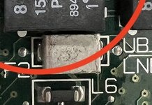
I just took a closer look at your photo. Is F2 supposed to look like that? It looks charred and pitted, with uneven edges and no markings on top.

IMG_5885.JPG
 

jmacz

Well-known member
The picture below is one I just found online, which looks the same, but less pitting? Or is that because I took a super close macro shot with my iPhone whereas the one below is further away and blurrier. No markings on top:

IMG_0023.jpeg

The fuse looks like two metal L shapes laying on top of each other with some substance in between the metal. And there’s continuity between the two pads with 0 resistance.
 
Last edited:

jmacz

Well-known member
Argh!!!

I need to start this entire analysis over again. I need to remember not to fully trust the Bomarc schematics. Lesson learned.

Screenshot 2023-11-07 at 6.13.35 PM.png
It should have been like this:

Screenshot 2023-11-07 at 6.13.35 PM 2.png

The schematic had the position of L6 and F2 reversed. Which completely explains why F2 cannot reach UB15 pin 2/7 (once I removed L6) and also explains why I thought UB15 pin 2/7 had a short to +5V because it has continuity to what I thought was the far pad of L6 but turned out that's just the next hop and the path to +5V is ...

UB15 pin 2 --> UB15 pin 7 --> L6 --> F2 --> +5V

So no shorts yet, no broken traces yet, UB15 seems fine, all the resistors and caps in the area are fine, no visible broken traces, and I'm going to ignore the 16 ohms between +5V and ground.

Will take a fresh look tomorrow as I only had a few minutes this evening and spotted this mistake. Jeez.
 

jmacz

Well-known member
Or another test: reinstall L6 but don't patch the broken connection yet. Turn on the computer and use your meter to measure the current between pin 3 and pin 4 (VCC and GND) of either ADB port with a 220 ohm series resistor. You should get about about 23 mA (5V divided by 220 ohms). I kind of suspect your ADB devices are not getting power from VCC, but are leeching power from the ADB Data signal.

22mA.
 

bigmessowires

Well-known member
So everything works? Usually that's a good thing, except you were hoping to find a problem that could explain your strange ADB-related video problems.
 

jmacz

Well-known member
No, it (the original problem) doesn’t work yet 😅

I had seen the 16ohm between 5V and ground which led me to look at UB15, and then had the L6/UB15 red herring due to the schematic. With that understood now and knowing that the 16ohm resistance is not an issue, and given the result of the current between 5V and ground on the ADB port, I need to start over. Looks like all the components are good (thus far).

I am going to focus on the monitor and video card, to record the sync signals when it happens, then work backwards from there. Will also try a few more monitors. And also try a few more PSUs to see if I can ensure I understand why one works while the other doesn’t. And hopefully figure this out.

The monitor issue is easy to repro. The SCSI is much harder to repro. Quite possible they are two different issues although the SCSI problem has never reproduced with external power provided and the video issue doesn’t happen with the other PSU so it seems power related. Need to look at the SCSI power as well.
 

jmacz

Well-known member
Summary of the Issues
  1. LCD monitor flickering (due to loss of sync) during rapid ADB mouse movements and/or keyboard key presses (easy to repro).
  2. SCSI IO errors if the device is relying on SCSI bus power instead of auxiliary power (hard to repro).
Things I Have Ruled Out
  • Monitor - tried 4 different LCD screens (different models/brands) and same problem on all of them.
  • VGA Cables - tried 3 different VGA cables and same problem on all of them.
  • Keyboard - tried 3 different AEKIIs and same problem on all of them.
  • Mouse - tried 2 different ADB Mouse 2s and 2 different Kensington Turbo Mice and a Glide Point, same problem on all of them.
Power Supplies
  • Issue happens on the stock PSU. 5V rail is around 5.1V.
  • Issue does NOT happen on an ATX PSU. 5V rail is around 4.9V.
What is causing the issue on the monitor?
From the blip of the message I see on the screen as it blacks out, looks to be loss of sync, so likely it's HSYNC or VSYNC.

I wanted to monitor HSYNC and VSYNC via a scope but didn't want to hack up a cable and I couldn't go from the video card side as the pins are hard to reach.

I had a project on the back burner to make my own DB15->VGA cable specifically for my SuperMac video cards at 1024x768 going to my NEC LCD monitors so that I can avoid the 10pin VGA adapter and reduce how much the cable sticks out behind my Mac. Also allows me to reuse the 10pin VGA adapter for other things. I already had one end of a DB15 cable and a VGA "breakout board" connector sitting at home for this project. So I got these out and wired up a cable.

I have been successful with 1256 and 1267 settings on the 10pin adapter. The 12 allows the monitor to be detected as a 19" 1024x768 monitor.

The 56 is Mode 2 (composite sync) and 67 is Mode 5 (separate sync). I saw this note from @dougg3 on @bigmessowires 's VGA adapter thread:
  • Switch 5 connects VGA HSYNC (13) to DB-15 CSYNC (3).
  • Switch 6 connects VGA HSYNC (13) to DB-15 HSYNC (15).
  • Switch 7 connects VGA VSYNC (14) to DB-15 VSYNC (12).
So 56:
  • Switch 5 connects VGA HSYNC (13) to DB-15 CSYNC (3).
  • Switch 6 connects VGA HSYNC (13) to DB-15 HSYNC (15).
And 67:
  • Switch 6 connects VGA HSYNC (13) to DB-15 HSYNC (15).
  • Switch 7 connects VGA VSYNC (14) to DB-15 VSYNC (12).
Tried the custom cable and it displayed picture properly (wired it for 1267). I then tried to repro the issue and I could not... huh... I then switched back to the 10pin adapter and the problem came back... hmm.. I then took a closer look at the 10pin adapter and noticed the 5 was partially on... so it was actually 12567:
  • Switch 5 connects VGA HSYNC (13) to DB-15 CSYNC (3).
  • Switch 6 connects VGA HSYNC (13) to DB-15 HSYNC (15).
  • Switch 7 connects VGA VSYNC (14) to DB-15 VSYNC (12).
I then tried various combinations:
  • 1256 - works, no issues.
  • 1267 - works, no issues.
  • 1257 - this isn't a combination listed on the instructions that came with the 10pin adapter, but this also works, no issues.
  • 12567 - does not work, reproduces my issue.
Hmm.. So 12567 is not a valid setting and I had SW5 partially on purely by accident, my intent was 1267. Clearly the issue is reproducing when both SW5 and SW6 are enabled at the same time which is not clearly not valid as VGA pin 13 is getting input from both CSYNC and HSYNC at the same time. But curious that it's stable when the mouse isn't moving? I wouldn't expect ADB activity to change anything.
 
Last edited:

dougg3

Well-known member
Ahh, that makes sense. Nice detective work! I always thought that 5 and 6 being on at the same time would be silly and was bad because you're basically shorting two outputs together. I still don't understand why they even mention it as a combination in the instructions.

It's interesting to hear a real world anecdote where it actually caused a problem. It definitely makes sense that CSYNC and HSYNC being shorted together could cause problems, but I can't explain why ADB activity seemed to be what pushed it over the edge.
 

bigmessowires

Well-known member
Weird. Glad you figured it out! Shorting CSYNC and HSYNC shouldn't really work at all, so any random little change in the computer's power consumption or data signal activity might have tipped the balance.
 
Top