• Updated 2023-07-12: Hello, Guest! Welcome back, and be sure to check out this follow-up post about our outage a week or so ago.

G3 All In One Wonky Display

3lectr1cPPC

Well-known member
Sounds like a great time to start replacing random components on the analog board until something changes...
 

AwkwardPotato

Well-known member
It's faint and quite buzzy (electric noise during boot sequence)
Shooting in the dark here but based on this, I almost wonder if there's a grounding issue with the tray holding the motherboard. Are there any obvious grounding spring tabs or similar on the tray that could've gotten bent out of place? With the machine unplugged from the wall and the RGB cable disconnected, do any of the pins on the personality card's AIO Video connector show continuity to the ground pin on the AC inlet? Feel like that would be too easy of an explanation though, because I can't see why the ground connection would fail only when the system warms up...
 

ried

Well-known member
Brought the Molar Mac out to the garage, which is approx. 60 degrees. After waiting a couple of hours, I started it up. The machine chimed and the screen worked as normal. Knowing that this was probably temporary, I started recording a video to try capturing the display and sound out from the internal speakers failing at the same time. I played with it for about 15 minutes before this happened:


AwkwardPotato

Well-known member
Looking through some low-res photos of the Wings personality card online, it looks like the audio side of it consists of the main Crystal audio IC, a TDA- series audio processor, and a handful of op-amps/power amps <snip>

Chances are the positive supplies to some/all of the audio op-amps will be derived from the system's +12V rail. Thinking about the video amp that techknight mentioned: while I don't have an AIO, I know for certain that the video amp in the early iMac G3 (similar analog board for the same type of CRT, designed by the same OEM) takes one +12V supply for the bias voltage. Wonder if there's a link there and that supply is dropping out for some reason...
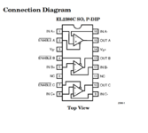
Going back to this too just to rule it out: looking at photos of the Whisper card, it appears there's an EL2386 triple op-amp IC just below the AIO video connector. Given its location and the fact that it has a fairly high bandwidth, it's safe to assume it's what's driving the R/G/B inputs to the monitor.

If the personality card is designed to run this video op-amp, and any of the audio op-amps, in dual-supply mode, said op-amps are likely the only things using the -12V rail in the system. In other words the -12V could fail as the system heats up and everything would work normally except the video and sound. All that's to say, what voltage do you all read on the -12V pin on the motherboard's molex connector (I believe it should be pin 12)? What about pins 3 and 14 of the EL2386, assuming there's enough room to reach a multimeter probe in there?

Screenshot 2022-12-18 041305.png
 

Torbar

Well-known member
Good news is, I've run mine for like an hour+ a couple of times this weekend and it's been stable. I checked the -12v and it's showing pretty much perfect.

Running it again without the shielding on, in hopes that it will do it again, so I can see if there's a drop in the -12v rail.


My last issue is, no sound. I put a different personality card in it(but that doesn't have the AIO or RGB connectors), and it did play through the headphones, so I guess my no sound issue is an issue with the personality card. I don't recall if I had sound or not previous to swapping the flyback, but whatever the case is, it seems like this Wings personality card's sound is totally dead. Both the wings and the non AIO personality card I have has the same sound chip, so i guess I could try swapping the chips between the two?
 

Torbar

Well-known member
(not to turn this thread into a sound related post. i'd edit the above comment, but am way past the 45 minute edit window. besides a final update on what the sound issue ends up being, I'll put any new sound issue questions in a new thread)

I swapped the chip, and have some success! sound works, but is incredibly quiet. I'll double check my soldering next week at some point. But at least i think it's safe to say my sound issue was not related to the video issue
 

ried

Well-known member
Good news is, I've run mine for like an hour+ a couple of times this weekend and it's been stable. I checked the -12v and it's showing pretty much perfect.
Good to hear that your machine is being sorted out. The display + sound issue still seems to be tied to temperature on mine. When it's cold, in the garage, works great. As the machine heats up to operating temperature, usually after 10 mins or so, it fails as shown in the video above.

Wish I knew why.
 

Torbar

Well-known member
Good to hear that your machine is being sorted out. The display + sound issue still seems to be tied to temperature on mine. When it's cold, in the garage, works great. As the machine heats up to operating temperature, usually after 10 mins or so, it fails as shown in the video above.

Wish I knew why.
When you have a chance, see if you can measure the -12v line on your power supply when it has the issue.

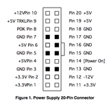
Looking at the power connector on the board, it's pin 12

1671472277239.png

AwkwardPotatos theory of that line going out of spec seems like a reasonable one
 

ried

Well-known member
When you have a chance, see if you can measure the -12v line on your power supply when it has the issue.

Looking at the power connector on the board, it's pin 12

AwkwardPotatos theory of that line going out of spec seems like a reasonable one
You bet. At the risk of sounding dumb, I'm relatively new to using a multimeter to measure board connectors. What should each lead be touching? Also, take one measurement when operating normally, and another during the failed state?
 

AwkwardPotato

Well-known member
Multimeter should be in voltage mode, with the black/negative probe touching any of the pins labelled "GND" in the diagram Torbar sent, and the red/positive probe touching Pin 12. Make sure the probe tips are actually touching the metal parts of the pins rather than the rubber insulation on the power cable. A measurement for both normal/failed states would be great, yes.
 

Torbar

Well-known member
Multimeter should be in voltage mode, with the black/negative probe touching any of the pins labelled "GND" in the diagram Torbar sent, and the red/positive probe touching Pin 12. Make sure the probe tips are actually touching the metal parts of the pins rather than the rubber insulation on the power cable. A measurement for both normal/failed states would be great, yes.
Yeah, I had to use a piece of breadboard wire(but a paperclip should work too). negitive probe you can just attach to a metal part of the chassis if you have a clip on connector.


If there's anything I can do as far as getting measurements or pictures or whatever to help troubleshoot ried's issue, let me know
 

ried

Well-known member
The darn thing won't go into fail state :LOL: Getting a nice and steady -12.24 volts while it's working properly.

IMG_6091.jpeg

Maybe it won't go into a fail state here in the garage while the back tray is open. Just too cold here? Will move inside and report back.
 

ried

Well-known member
Fail state measure +0.649 volts, and the really odd thing is that it's positive. How can it be positive on the -12v rail?

IMG_6092.jpeg


Edit: Very steady at +0.646 to +0.649 volts. How odd!
 
Last edited:

AwkwardPotato

Well-known member
Fail state measure +0.649 volts
That's great to hear! So we know the root cause of this nightmare now. Not really sure why it would be positive either. If you get a chance, it would be great to have a few pictures of the power supply board (mostly of the back) so as to figure out what might've gone wrong on it.
 

ried

Well-known member
@AwkwardPotato's 12v rail theory is spot on in my case. Real-time proof:


I'll pull it apart to get pics of the power supply board in the next day or so.
 

ried

Well-known member
Photos of the power supply as it sits in the machine.

IMG_6104.jpeg
IMG_6103.jpeg
IMG_6096.jpeg

IMG_6102.jpeg

IMG_6101.jpeg


IMG_6098.jpeg

IMG_6099.jpeg


IMG_6100.jpeg

Cap goo here?

IMG_6105.jpeg
 
Last edited:

joshc

Well-known member
Great investigative work so far! I don't own a molar Mac but, and I may be stating the obvious here, but something is drifting out of spec as it warms up. Diagnosising it will be a case of identifying which circuit/components supply the -12V rail. Without schematics this is a little trickier but not impossible. Starting with a recap is probably the 'easiest' thing to try (still cumbersome, judging by those boards and not knowing how difficult they are to remove and how many caps there are), but it would at least rule those out.
 

AwkwardPotato

Well-known member
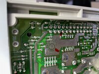
From the photos it seems like some of the solder joints on the power supply->motherboard connector have annular cracks. Couldn't hurt to reflow/add more solder to those just to rule them out, although both Torbar and Unknown_K reported that they'd reflowed solder joints to no avail.
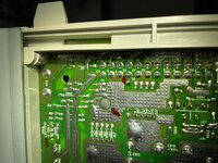
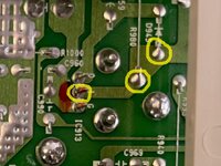
Failing that, it appears the -12V is generated by linear regulator IC913, just down and to the right from the PSU->mobo connector, which also looks like it has cracked solder joints. If reflowing them still doesn't change anything, I'd probe the I pin of the regulator (or one of the less cramped components connected to it) to see if it's getting anything at its input (any of the following spots, doesn't matter which):

IMG_6101 (2).jpeg

The voltage at the I pin should be a more negative one, probably -15V or more. If there's no voltage there in the failed state it means the problem is upstream of the regulator.

EDIT: And hopefully not being overly annoying by saying this, but be careful if you decide to take measurements on a live power supply! Don't brush your hand against the board; especially avoid the right-hand side where the line voltage comes in. Shit can hurt big-time ;)
 
Last edited:

Torbar

Well-known member
I didn't reflow any solder joints on the power supply side, so probably not a bad idea to do that(and for me to do that as well)
 

ried

Well-known member
From the photos it seems like some of the solder joints on the power supply->motherboard connector have annular cracks. Couldn't hurt to reflow/add more solder to those just to rule them out, although both Torbar and Unknown_K reported that they'd reflowed solder joints to no avail.
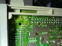
At the risk of sounding optimistic, I think you're right. They're hard to photograph, but several annular cracks in the solder around the power supply->motherboard connector here, included those labeled 12v.

IMG_6109.jpeg

IMG_6113.jpeg
IMG_6114.jpeg
 
Top