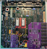
A little update: The 74259 sub-circuit can now be activated without causing issues. The Mac boots normally, recognizes the RAM expansion, and seems to function correctly. The only changes I made since the prototype build were to add pull-ups to A22 and A23 and patch the code of the ROM-INATOR ROM at 0x0003F0. Since this circuit was intended for the Mac 512KE (MacPlus ROM) ,I'll keep it activated and set as the default.
View attachment 78727
I'm trying once again to understand this portion of the circuit for the MacSnap.
The output of the 74LS259 controls OEb of the 74LS253.
OEb of the 74LS253 being HIGH forces its output Zb LOW.
Output Zb of the 74LS253 being LOW forces the 74LS139s to only provide CAS to either CAS2F&CAS3F (system 512K) or CAS4F&CAS5F, so only 1MB of memory is possible. CAS0F&CAS1F and CAS6F&CAS7F are disabled, so 1.5MB or 2MB are not possible.
All of this going the other way allows all CAS#F signals to be enabled, so 1.5MB or 2MB is possible.
The output of the 74LS259 is a latched bit, so it maintains its output until it is changed.
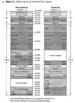
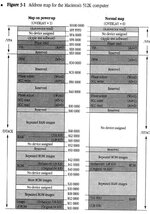
Its output is changed only when the system writes to an address within the range 0x200000-0x27FFFF or 0x280000-0x2FFFFF (A19 being the deciding factor between the two ranges).
Writing to 0x200000-0x27FFFF sets the output of the 74LS259 to LOW which enables CAS provisions for all CAS#F lines.
Writing to 0x280000-0x2FFFFF sets the output of the 74LS259 to HIGH which disables CAS0F&CAS1F and CAS6F&CAS7F.
Reading from these address ranges makes no changes to this latch.
Was there any special software which came with the MacSnap board? Perhaps the purpose of this memory mapped latch is for a software controlled configuration change?
On another train of thought following Builder68's theory: Maybe the Plus ROM does something funny in these address ranges? In a Ghidra disassembly of the Mac Plus ROM, is there a simple way to search for writes to specific ranges in memory (such as these two range in question)?
It's strange that the system would write to these ranges which are mirrors of RAM, so I don't think it would typically do so. In fact, a 4MB mod would not be possible, since 0x200000-0x2FFFFF lands within the 4MB memory range (0x000000-0x3FFFFF) and writes to 0x280000-0x2FFFFF will disable a portion of RAM.
Here is the possible memory mapping and mirroring for RAM with regard to 1MB blocks:
0x000000-0x0FFFFF : 1st 1MB
0x100000-0x1FFFFF : 2nd 1MB or 1st mirror of 0x000000-0x0FFFFF
0x200000-0x2FFFFF : 3rd 1MB or 2nd mirror of 0x000000-0x0FFFFF or 1st half of mirror of 0x000000-0x1FFFFF
0x300000-0x3FFFFF : 4th 1MB or 3rd mirror of 0x000000-0x0FFFFF or 2nd half of mirror of 0x000000-0x1FFFFF