• Updated 2023-07-12: Hello, Guest! Welcome back, and be sure to check out this follow-up post about our outage a week or so ago.

Basket Case PowerBook 180c

ravuya

Active member
That's some really dedicated work, impressive commitment. I wonder if it is feasible to make a new flat flex cable using e.g. an Oshpark flex PCB service? Probably not cheap, and likely would take just as long to do all the measurements.

Any luck with the trackball bezel? I'm looking for some rollers for my 145, but I also don't want to buy the entire trackball assembly. Now I'm considering taking some measurements and following your lead to make my own ;)


sutekh

Well-known member
Well, all is not yet well I'm afraid. After buttoning it up post LCD recap, I noted two things:

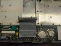
  • ~1/3rd of the keyboard didn't function. Prior to this point, I hadn't done any typing whatsoever, so I imagine this was a pre-existing condition. I removed and inspected the keyboard, ribbons, etc., and noted nothing obvious. I found a few posts blaming similar behavior on the interconnect board and re-flowed it just in case to no avail. Starting to suspect the interconnect board's ribbon cable, on a hunch I booted up with the chassis split in half and the cable, which looks like it's been bent and reinstalled dozens of times, accessible for a bit of prodding. Sure enough, if I wiggled and poked the cable, portions of the keyboard intermittently came back to life. Okay, so some of it's solid conductors had apparently exceeded their flex quota. Using more spare cables (this time an 80-pin U-ATA), I rebuilt that guy, and the keyboard is happy :)

    IMG_20200815_195030.jpg
     
  • Problem number 2 is intermittent and its culprit less readily apparent unfortunately. About 50% of the time (although that seems to be increasing to most of the time), the backlight turns off and stays off during the boot process. If I power down and reboot, I get a backlight, happy Mac, starting MacOS, and about the time extensions would start loading, it shuts off. I of course suspect that it's something related to when the brightness goes software controlled, but I've booted without extensions and from a 6.0.8 install disk with similar results. Seems nearly identical to the behavior outlined in this thread here:
     
    The final posts there seem to question the PS, but I'm using a combination of a 10A regulated bench supply and fully charged LiPos. Stable voltage and plenty of current, at least at the point of input, are not the problem. Unless anyone has any ideas, it's coming back apart and I'll have to get after the inverter and interconnect boards with the DMM / scope. Grr... I thought I was out of the woods!

Once it's fully up and running though, I'm super excited to build this guy a Li-Ion battery. Owing to it's ideal voltage (7.5v with a 2S Li-Ion providing 7.4v) and the fact that the batteries just have a pos / neg connector (no fancy serial check), this should be much easier than my currently stalled-while-I-mess-with-this-180c Duo Li-Ion project :)

 
Last edited by a moderator:

sutekh

Well-known member
That's some really dedicated work, impressive commitment. I wonder if it is feasible to make a new flat flex cable using e.g. an Oshpark flex PCB service? Probably not cheap, and likely would take just as long to do all the measurements.

Any luck with the trackball bezel? I'm looking for some rollers for my 145, but I also don't want to buy the entire trackball assembly. Now I'm considering taking some measurements and following your lead to make my own ;)


I hadn't thought about having one fab'd, but why not? I've used Oshpark a few dozen times for various FR4 prototypes, but didn't know they did flex. That's awesome! Now I'm wishing I hadn't been so quick to slice-and-dice my original cable. I'll save all the bits just in case...

I did get a lead on a bezel and port cover from a gracious member, so by midweek once those and the 3A power adapter I also ordered arrive, this thing should be 100% (minus the battery of course, but that'll be another thread...)

Finally, I did manage to get issue #2 outlined above resolved. After dismantling / reassembling the chassis several times and poking and prodding around to recreate the behavior, I zeroed in on the  72-pin interconnect cable (yes, the one I'd just rebuilt). I determined that it isn't a problem with the cable, however, but rather the connector. The interconnect cable connector has a very small cavity it sits within in front of the interconnect board and above the daughter board. Any side to side or fore/aft load on the cable when compressing the halves of the case together will cause connection issues. I carefully routed and creased the cable in such a way that the connector slides right into its narrow pocket during reassembly and all is well.

This is probably what was wrong with my KB in the first place, now that I understand the issue better. Ah well, no harm done in replacing the ribbon. This is another design weakness frankly and is, I suspect, the reason others have reported similar issues and end up replacing the interconnect board as a solution. Given the pin density, limited physical space, and minimal insertion force, this connector really should have lock clips or something to retain it securely.  Something I may seek to add if it continues giving me grief. For now though, I guess it's time to update my sig to include a functional PB-180c...

 
Last edited by a moderator:

vldmr

Member
Interesting story - that I am almost reliving. Yes, I also was looking to get 180c for a long time, and  I got one recently for low offer. Mine was in better shape - no leaking battery. Hinge screws ripped out, burned electrolytic caps on inverter (?) board, hard drive with click of death - but the flex cable is in one piece. I glued hinge to screen bacl wall with epoxy, replaced burnt caps, backlight works, but the screen stays blank (white).

I tested and confirmed continuity of all traces on flex cable, checked with scope that there are some live waveforms on flex cables leading to LCD glass from screen logic board, so seems something is fed to the glass, but not even shade of grey pattern or mouse pointer is visible.

What make me wonder is that voltage on wide (power?) trace of flex cable is only 2.3V - I would think at that time the lowest voltage used was 3.3V. If yours screen is still opened and accessible, could you check what is supply voltage is fed to LCD on yours working system. Thanks


sutekh

Well-known member
If yours screen is still opened and accessible, could you check what is supply voltage is fed to LCD on yours working system. Thanks


It's buttoned up at the moment, but I'll be opening it up in coming days to 1) send 5v (probably from the ADB since it's right there and fused) into pin-5 of the SCSI HID-30 connector for term power and b) to yank the Global Village modem and install a ribbon cable in its place so I can start testing the wifi modem replacement board I have a thread about over in the Hacks forum.

I'll meter the power traces when I do and let you know...

BTW, interested to hear how your hinges hold up. I tried JB-Weld at first, but it eventually gave way. Ended up dismantling and cleaning the hinges, then re-lubricating to relieve tension (helped somewhat) and also drilled pilot holes through all 4 knurled brass inserts out the back of the clamshell and sent some 2.5mm x 6mm screws in from the other side to pin everything together. They're obviously visible, but after counter-sinking the holes, I think they look just fine. There's plenty of remaining unused thread within the inserts for them to grab onto. Quite solid now.

 
Last edited by a moderator:

vldmr

Member
BTW, interested to hear how your hinges hold up. I tried JB-Weld at first, but it eventually gave way. Ended up dismantling and cleaning the hinges, then re-lubricating to relieve tension (helped somewhat) and also drilled pilot holes through all 4 knurled brass inserts out the back of the clamshell and sent some 2.5mm x 6mm screws in from the other side to pin everything together. They're obviously visible, but after counter-sinking the holes, I think they look just fine. There's plenty of remaining unused thread within the inserts for them to grab onto. Quite solid now.
Interesting - I discussed this repair with a friend of mine, who I trust with anything mechanical, and he also strongly advised on through holes with brass plates on outside. I almost went that route, but then there was a discussion on vcfed forum about fixing hinges, and two members there vouched that epoxy would be good enough, given that the hinge is loosened with fresh lubrication. So I decided there is nothing to loose trying epoxy on internals, and I always can proceed with through screws if that would fail. I just flooded the area on the back panel of the screen around the hinges with epoxy - I had the screws with original inserts in place during the application of epoxy. So now I have plastic back-panel permanently attached to hinges, the front panel still is removable and fixed with screws. So far it holds fine, I did not notice any problems in epoxy cracking, but I am yet rotating the screen slowly and carefully.

I lubricated the hinges with WD40 and gave it a good workout by inserting the pin in electric drill and rotating it for few minutes prior to assembling with epoxy.


vldmr

Member
What make me wonder is that voltage on wide (power?) trace of flex cable is only 2.3V - I would think at that time the lowest voltage used was 3.3V. If yours screen is still opened and accessible, could you check what is supply voltage is fed to LCD on yours working system. Thanks
Looks like sutekh moved on to new adventures, so I decided to try to answer my own question myself. I hooked a lab power supply to power rails on LCD assembly, and after powering machine on tried to apply 3.3V at first - nothing changed, no current flow from PS into circuit. After that I took a deep breath and cranked PS to 5V -- aand waddoyouknow: a nice crisp image appeared on LCD, and PS showed 0.1A current drain.

So, the supply voltage for LCD on 180C is indeed 5V, and in my case it is at fault, so next I will be looking for a power supply circuits on PCB. Of course, it might be a leaky electrolytic capacitor somewhere around power rails. 


sutekh

Well-known member
Looks like sutekh moved on to new adventures, so I decided to try to answer my own question myself. I hooked a lab power supply to power rails on LCD assembly, and after powering machine on tried to apply 3.3V at first - nothing changed, no current flow from PS into circuit. After that I took a deep breath and cranked PS to 5V -- aand waddoyouknow: a nice crisp image appeared on LCD, and PS showed 0.1A current drain.

So, the supply voltage for LCD on 180C is indeed 5V, and in my case it is at fault, so next I will be looking for a power supply circuits on PCB. Of course, it might be a leaky electrolytic capacitor somewhere around power rails. 
Whoops! I forgot all about it TBH. Glad you identified the culprit!


vldmr

Member
So, the supply voltage for LCD on 180C is indeed 5V, and in my case it is at fault, so next I will be looking for a power supply circuits on PCB. Of course, it might be a leaky electrolytic capacitor somewhere around power rails. 
It turned out the 5V power supply for LCD is actually located on the opposite side from LCD flex cable connector - on inverter board, which produces it from 7.5V

I believe I mentioned before that my inverter board had couple of burnt capacitors, which I replaced, and was happy with working backlight. I though that indicated that inverter board was fine. Who would have though that this same board also supplies low voltage.

Tracing showed the 5V comes out of chip labeled SL90067 of unknown breed - at least I was not able to find relevant datasheet for that. Here is the link to photo of the board for anyone curious. So everything lead to replacing the inverter board, which have not appeared on ebay in recent history.

Then I though to myself - what do I have to loose: lets fix it with household means. I pulled out 5V linear voltage regulator, slapped it on underneath the board, and put the machine back together.

Decisive success! The image appeared right away, perfect quality, and even brightness regulator does work. I am one happy camper now.

Except that during all these manipulations the epoxy that I used to reattach display to hinges cracked. After which I proceeded with more radical fix by drilling through holes in plastic back cover of display and putting longer screws with metal plates and nuts on outside surface. Looking at the result I feel that computer got some nice steam-punkish character from this mod. So I am still happy camper.


tedcy

Member
Hello friends. Anyone has a PowerBook 180c LCD ribbon cable that he can sell? Or knows where I can get one? I tried the above method (it was a pain) and I'm waiting for the tantalum caps to arrive before I can fully test it.... but even if it works I don't think it will last long (my soldering skills are amateur to intermediate at best :).
 
Top