Basket Case PowerBook 180c

sutekh

Well-known member
Well, I officially need my head examined. I threw a low offer out on an untested "parts" PB 180c, and to my surprise it was accepted and arrived today in one piece. It's a wreck though. Its installed aftermarket NiCad has leaked and was fused in place. Plastic at the hinges is of course broken. It's filthy dirty, missing the ring around the trackball and the port cover, and didn't include a power transformer. I've wanted a 180c for years (had a 170 in college and lusted after them), but planned to hold out for a nice one. What am I doing with this basket case?

I was able to delicately pry the rotten battery out and get the case open, and to my relief, nearly all of the battery leakage is isolated the the battery compartment. I pulled every board out and both them and the chassis just to be sure. After a quick cap inspection, I decided to try feeding it 7.5.v from my bench power supply. Chimes of death :'(  I had a spare daughter and memory board knocking around, so swapped those in and was this time greeted by the normal startup chime. Great! And a blank screen. Less great.

The floppy clicked, the HD started chattering. Something was happening, but LCD remained blank. Having been on the hunt for the right (i.e., not this one) 180c for a while, I'm all too aware that their LCD ribbon cables are a major weakness. Fearing the worst, I opened the screen and, sure enough. Cut completely in half right at the hinge. Damn. Guess I'm going to be splicing together a ribbon cable :O  I've seen a few threads where others have tried this with varying degrees of success. Seems like the problems arise from using individual, unshielded conductors that end up picking up interference. I'm planning to sacrifice an 80-pin LVD SCSI cable owing to it's densely packed conductors. Wish me luck...


sutekh

Well-known member
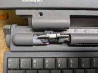
Although every bit as tedious as I'd imagined, it's going pretty well thus far :)  Thankfully the copper is plenty thick and the first half is done with each conductor metering clean with low-resistance. I ended up chopping apart two SCSI cables, the first having solid conductors where I'd definitely prefer stranded in this situation, but c'est la vie. I'll put a bit of resin over the junction, tape it up, and finish the other side tomorrow. Hope to have video output to show for it!

IMG_20200811_010454.jpg

 
Last edited by a moderator:

techknight

Well-known member
Yikes!! Yea that definitely takes the patience of a saint. No way I could do something like that these days, id get frustrated too easily. 


sutekh

Well-known member
Yikes!! Yea that definitely takes the patience of a saint. No way I could do something like that these days, id get frustrated too easily. 
Yeah, I had to call it for the night after doing the first half. Gotta space the misery out a bit!

While contemplating cable routing, I think I've decided to take a page from Duo's book. No doubt in response to the issues with PB 1xx, Apple routed the Duo's LCD cable around the hinge to create much less overall movement / flex (and therefore fatigue) of the ribbon. I'm a bit worried that where the red conductor rubs against the hinge could ultimately wear / short, but think I can prevent that by routing it carefully or perhaps padding it a bit. Last step is to solder the 2nd side in situ, which I'm not really looking forward to :/

IMG_20200811_093102.jpg

IMG_20200811_093905.jpg

 
Last edited by a moderator:

techknight

Well-known member
Is this the U-ATA style ribbon cable? the kind that has double the mount of wires, but skinny wires? that would be ideal. 


sutekh

Well-known member
Is this the U-ATA style ribbon cable? the kind that has double the mount of wires, but skinny wires? that would be ideal. 
This is from a 68-pin UW SCSI cable, but the conductor pitch is the same as those 80-pin U-ATA cables. I used this vs. any of the U-ATAs I had in my box owing to this particular cable's flexibility (very finely stranded 30AWG wire) and because I have dozens of them laying about from my server building days :)

 
Last edited by a moderator:

Papichulo

Well-known member
one thing i try whenever i get one of these junk 100 series powerbooks is use tape and tape the ribbon cable all around so it wont tear as easy 


OleLila

Well-known member
Nice...be careful plugging and unplugging the tab connector as they can  (eventually) displace especially after you solder to it. I tried some of this but not as clean as you are to this point, it semi worked but it was so tedious I haven't gotten back to it. Still kicking myself for not being more careful putting the hinge cover back on.


I will be curious to see how it works out as far as using the same gauge wire for power/grounding/signals as they are different sizes and separated in the original ribbon cabe.

 
Last edited by a moderator:

sutekh

Well-known member
I will be curious to see how it works out as far as using the same gauge wire for power/grounding/signals as they are different sizes and separated in the original ribbon cabe.
Thanks! Yours is one of the threads I reviewed and alluded to above. Thanks for posting and providing inspiration. It's hard to tell in my first image, but I added additional conductors for the two largest power / gnd traces on the left side. 3 and 2 respectively. I did not, however, double up the 3 wider RGB traces. Doing so, I worried, would have prevented my ribbon from routing behind the hinge or through the ferrite SMI suppression ring. I hope it doesn't matter, as at it's narrowest point, the conductors in the original ribbon are smaller and closer together than anything I'm recreating, but I'll know more after buttoning it up this afternoon and will report back...

The chronic crumbling plastic behind the hinge issue creates a perfect storm where an already dubious design is exposed to even more stress. My original ribbon was ripped in almost exactly the same location no doubt for the same reason.

 
Last edited by a moderator:

sutekh

Well-known member
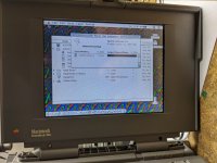
Boom! Works like a champ. Clear and crisp with all colors reporting for duty.

IMG_20200813_021621.jpg

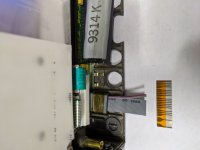
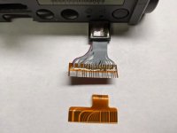
Here's the other half of the splice with a bit of the original end below it. After stripping away the insulation, fluxing, and tinning, I landed the conductors, then covered the solder pads with a thin coat of UV activated resin (if you don't have a Bondic pen, I can't recommend them enough!)

IMG_20200812_212417.jpg 
 

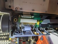
And finally, here's the 2nd end of the ribbon installed.

IMG_20200813_021758.jpg

I guess now that the real show stopper is corrected, I have to set about sorting the rest of this thing. The installed 160M drive was DOA (clunk of death), so I installed a spare 500M with 7.6 on it. for testing Between that, the LCD cable, fried memory module, leaky battery, and busted hinges, I can't help wondering if I'm resurrecting someone's parts unit :)

Oh, and it's missing the trackball bezel. If someone happens to have a spare they'd part with reasonably, it'd sure beat paying the going rate for the whole assembly on eBay...


Byrd

Well-known member
Nice work - I admire your patience resoldering that ribbon cable - any further tips, what temp did you have your iron at to get the solder to take on the copper connectors?

The PowerBook 180c is such a nice machine - all that colour, speed and (chunky) portability in the day would have been amazing.  I assume Apple didn't sell too many owing to the initial cost of ownership; the venerable PowerBook 170 would have been the professional 'book of choice more in the day.


BadGoldEagle

Well-known member
Wait, I thought you couldn’t swap orange flex cables with normal ones? Does that mean one could theoretically repair M5126 Backlit Portable display cables this way?

Kudos BTW! At least it’ll be sturdier than the original. 


ArmorAlley

Well-known member
Well, I officially need my head examined. I threw a low offer out on an untested "parts" PB 180c, and to my surprise it was accepted and arrived today in one piece. It's a wreck though. Its installed aftermarket NiCad has leaked and was fused in place. Plastic at the hinges is of course broken. It's filthy dirty, missing the ring around the trackball and the port cover, and didn't include a power transformer. I've wanted a 180c for years (had a 170 in college and lusted after them), but planned to hold out for a nice one. What am I doing with this basket case?
As a child of the Seventies, only one TV-Intro came to mind: 'Gentlemen, we can rebuild him, we have the technology...'

https://www.youtube.com/watch?v=0CPJ-AbCsT8

Well done on your conservation effort. I am happy to see people combatting the natural disasters that come with old age. I have a spare LVD SCSI cable that I can contribute, if you are missing one.


Papichulo

Well-known member
Boom! Works like a champ. Clear and crisp with all colors reporting for duty.

View attachment 36447

Here's the other half of the splice with a bit of the original end below it. After stripping away the insulation, fluxing, and tinning, I landed the conductors, then covered the solder pads with a thin coat of UV activated resin (if you don't have a Bondic pen, I can't recommend them enough!)

View attachment 36448 
 

And finally, here's the 2nd end of the ribbon installed.

View attachment 36449

I guess now that the real show stopper is corrected, I have to set about sorting the rest of this thing. The installed 160M drive was DOA (clunk of death), so I installed a spare 500M with 7.6 on it. for testing Between that, the LCD cable, fried memory module, leaky battery, and busted hinges, I can't help wondering if I'm resurrecting someone's parts unit :)

Oh, and it's missing the trackball bezel. If someone happens to have a spare they'd part with reasonably, it'd sure beat paying the going rate for the whole assembly on eBay...
i have 2 extra trackball assemblies if your interested 


OleLila

Well-known member
Yeah! Great job and good eyes....So there is hope...I would try the same except for the part about "be careful plugging and unplugging the tab connector as they (the tab contacts) can  (eventually) displace"........its pretty cramped in there but looking at taking the header off of the inverter board and soldering straight to the board.

 
Last edited by a moderator:

sutekh

Well-known member
Nice work - I admire your patience resoldering that ribbon cable - any further tips, what temp did you have your iron at to get the solder to take on the copper connectors?


Thanks! I did some testing on a sacrificial section of cable, and as OleLila mentioned, it'll delaminate if too hot for too long. I ran my iron cooler than I usually would for the Sn/Ag solder I was using at 350° C. After scraping off the insulation with a hobby knife, I pre-tinned the stripped conductors before landing them and used flux paste all in an effort to minimize how long the ribbon was hot.

As a child of the Seventies, only one TV-Intro came to mind: 'Gentlemen, we can rebuild him, we have the technology...'

https://www.youtube.com/watch?v=0CPJ-AbCsT8

Well done on your conservation effort. I am happy to see people combatting the natural disasters that come with old age. I have a spare LVD SCSI cable that I can contribute, if you are missing one.


Haha! Technology, time, and patience. Thanks for the SCSI cable offer. I'd take you up, but I have a file box literally overflowing with SCSI cables :) I ended up scrapping the idea of an LVD, as they have twisted pairs, and just used a narrow-pitch 68-pin UW.

i have 2 extra trackball assemblies if your interested 
Most definitely. I'll send you a PM. Thanks!
 

Yeah! Great job and good eyes....So there is hope...I would try the same except for the part about "be careful plugging and unplugging the tab connector as they (the tab contacts) can  (eventually) displace"........its pretty cramped in there but looking at taking the header off of the inverter board and soldering straight to the board.


That would definitely work. Had the cable repair not gone well, that was my plan B. Not sure which side of yours is now damaged, but on the PB side the connector is a through-hole part. Soldering to its pins would be much easier than messing around with the cable TBH.

 
Last edited by a moderator:

OleLila

Well-known member
The other thing here is the distances and bends in the cable., the right length to bend, flex and close the screen .....Do you have a picture of the back of the lcd w cable in place?


sutekh

Well-known member
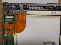
I still have it apart pending today's delivery of my Mouser order for a re-cap, so here's a pic of the LCD with cable. Unfortunately I can't really measure the length with any accuracy without pulling it all apart, removing the hinge, and disconnecting the cable--not something I'm super anxious to subject it to, but hopefully this gives anyone attempting to recreate enough to go on. As mentioned above, I spun the cable around the hinge in an attempt at strain / fatigue relief. Also as a means of jogging the cable over since the original has a couple of 90deg bends built into it.

IMG_20200813_112743.jpg

Only thing I think I'd do differently is to stagger the contact points up and down a bit so your not trying to solder tiny little wires to tiny little pads right next to one another. Only on the LCD side though. I don't think there's room for that inside the chassis.

 
Last edited by a moderator:
Top