Power LED comes on and there is a click from the speaker. CPU quickly gets quite hot. No POST, no video.
What should I try next?
Here is what I have tried/observed so far:
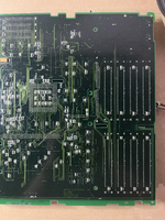
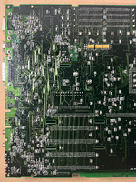
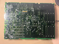
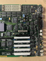
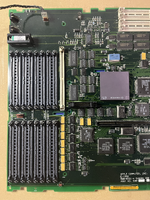
Logic board photos below and attached. Appears to be in good condition. There was minimal corrosion here and there which I mostly cleaned up.

What should I try next?
Here is what I have tried/observed so far:
- Tried multiple RAM configurations with tested good SIMMS following Apple's Memory guidance
- There is a tested good PRAM battery in the logic board
- Tried both with the original PSU (which is at least providing good voltages) and an ATX PSU adapted following Geekdot's guide
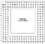
- CPU is XC68040RC33E which the seller claimed was pulled from a working system.
- 8 pins fell off the XC68040RC33E CPU that was in the machine. No visible corrosion; possibly I damaged it while removing it...?
- Scoped CPU pins following attached pinout diagram
- No waveform on TK, BCLK or PCLK. There is a sine wave coming out of the nearby 66.67 MHz oscillator.
- I am using a Zoyi ZT-703S oscilloscope, which I believe has sufficient bandwidth so I should see a 33 MHz square wave on one of the clock pins
- VCC is +5V
- RST is +5V
- No waveform on TK, BCLK or PCLK. There is a sine wave coming out of the nearby 66.67 MHz oscillator.
- Reset and interrupt buttons are flaky, but they are not sticking closed
- At the logic board power connector, with no PSU plugged in, there is low resistance (11-12 ohm) between +5v and ground, but maybe that is normal...?
Logic board photos below and attached. Appears to be in good condition. There was minimal corrosion here and there which I mostly cleaned up.