• Hello MLAers! We've re-enabled auto-approval for accounts. If you are still waiting on account approval, please check this thread for more information.

IIci NuBus Cards Not Detected - Trying Everything

I am struggling to get my IIci to detect/use NuBus cards. I have a Radius PrecisionColor 8-24X, three different Ethernet cards, and a Radius Rocket. None of them seem to do anything in any of the slots. It's as if they aren't even there. The Rocket gets warm (slots appear to be properly powered), but that is the only thing the cards do. No lights on the NIC's, no video signal or detection of the PrecisionColor. No combination of drivers seems to have any effect. TattleTech shows only the onboard video as a NuBus device.

Here is what I've already tried:
  1. Full recap. -- verified continuity, no pads ripped or damaged.
  2. Replaced battery with a CR2023 (Lithium) based solution. -- verified correct voltages are making it to the board.
  3. Replaced PSU with PicoATX + homemade adaptor. -- Verified correct voltage, very low ripple, good performance under load. -- no faults.
  4. Double checked all replaced capacitors for good connections, correct polarity, and continuity with their destination circuits on both ends -- no faults.
  5. Checked every trace in the vicinity of the NuBus slots that looks anything but factory condition for contenuity -- no faults.
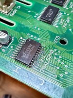
  6. Checked the traces that go under the replaced capacitor C16 (below the NuBus slots -- appears to help stabilize the voltage rails for the bus) -- no faults.
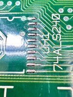
  7. Reflowed the solder on UH1, a buffer/inverter chip for the bus just below C16. Checked pins for continuity with the pin's trace's destinations -- no faults.
  8. Removed UH1 and replaced it with UH3 (same chip, but farther from leaky C16) from another IIci, verifying continuity again. -- no faults.
  9. Checked every pin of every slot to verify no slots have a broken circuit between slots. -- no faults.
  10. Checked adjacent pins to verify no cross-pin shorts (except for intentional shorts, such as multiple power or ground pins). -- no faults, but many nearby pins show ~340 ohms. I thought this was bad, but my second "donor" board had the same readings, so I think this is normal/ok.
  11. Carefully cleaned and snooped under all chips, especially the "bus tranciever" chips, UH1-3, UH5 (68882 NPU), UK2 ("NUCHIP30") looking for any shorted or broken connections. -- nothing out of place, no change.
  12. Repeatedly given the board an extensive cleaning, including shooting water under every chip and trying to blast anything out of the slots with air, rubbing alcohol, and water, followed by a complete drying via air purifier exhaust. -- no change.

IIci's seem to be notoriously difficult to restore.

The board has no visible battery damage (it appears that the battery was removed before long-term storage). It had a bit of capacitor leakage, not enough to visibly corrode any traces, but enough to crust up some of the chips near the caps.

The IIci boots fine from either an external Blue SCSI v2 or BMOW ROM-inator II, and will even use a 50MHz Daystar 68030 accelerator in the PDS with no issues. Sound works fine, ADB works fine, onboard video, all ram slots, etc. Everything seems to work, except NuBus cards.

What could I be missing? What diagnostics might help identify the issue? I have a second donor board (terrible battery explosion case) that I could transplant other components from.

Thank you for any help!
 
Went through this myself a few years back on my last IIci. Wound up eventually just grabbing another board. Something failed on the board, causing the slots to be dead, even with a brand new 74ALS240 chip installed at UH1.
 
Replaced battery with a CR2023 (Lithium) based solution. -- verified correct voltages are making it to the board.
I just want to clarify... do you mean you checked the voltages for the battery.. or the PSU voltages getting to the relevant pins on the nubus slots themselves? The reason I ask is I recently had an issue with a IIcx where certain things weren't getting power, and I think that also included the nubus slots from memory.. turned out a fuse on a +5v trace had failed.
 
I just want to clarify... do you mean you checked the voltages for the battery.. or the PSU voltages getting to the relevant pins on the nubus slots themselves? The reason I ask is I recently had an issue with a IIcx where certain things weren't getting power, and I think that also included the nubus slots from memory.. turned out a fuse on a +5v trace had failed.
Thank you for your ideas.

I meant that I verified that the replacement battery was sending it's voltage to the mainboard. I've had these adapters sometimes not properly seat in the PRAM battery holder and make intermittent contact. That isn't happening here.

I have also verified that when powered the proper voltages (+12, -12, +5, 0) are on the big barrel electrolytic capacitors (power filtering capacitors C14, C15, C17 near the power supply connector, and C8 just above the NuBus slots). I also get the good voltages (I think are correct?? GND/0 and +12V-- if I remember correctly) on replaced surface-mount capacitor C16 just below the NuBus slots.

Looking for any obvious problems, I already verified that the rectangular metallic fuses F1-F3 near the rear ports are not blown. These fuses appear to be used to protect the mainboard and peripherals form each other. However, it is a good point. Are there other, perhaps smaller fuses I should be checking? If the IIcx has a fuse for the NuBus ports, it seems likely that the IIci does as well, but I don't see anything obvious. I feel like I'm probably just missing it. Maybe it's one of the seed components on the back?

I haven't matched up power continuity with a nubus connection diagram. I think that's next on my list. Does anyone have a better NuBus pinout diagram than the listing here: http://www.bitsavers.org/pdf/ti/nubus/2242825-0001_NuBus_Spec1983.pdf ?
 
Ok. Reviewing the NuBus spec sheet and this partial schematic I found: https://www.macdat.net/files/pdf/apple/schematics/bomarc/mac_iici.pdf, I verified that the +12V, -12V, GND, and +5V connections are all continuous, low-resistance to the correct power filtering capacitors. However, I did notice that the -5V rail appears to float (this document seems to suggest this is normal, though https://bitsavers.computerhistory.o...ocessor_Platform_Developers_Guide_Nov1989.pdf).

More distressingly, the resistance between +5V and GND is a mere 14.58 Ohms.

I checked my donor board, and it also measures a relatively low 18.56 Ohms between +5V and GND, so perhaps this is ok?
 
Curious.. I wonder what could be causing that. Bad resistor perhaps?
It appears that this is normal. Just so many TTL circuits between +5V and GND on this board. https://tinkerdifferent.com/threads/macintosh-iici-5v-to-gnd-resistance.4117/

My next step will be to measure the CLK (C32), RESET (C1), ACK (A28), START (C28), and TM0/1 (A5, C5) signals on slot E with an Ethernet card in slot C. I am hoping to see a good 10 MHz, 75/25 duty cycle signal on CLK. RESET should assert (low) and then release (high) when starting up or restarting. START and TM0/1 should show activity when cards are scanned at startup and when running TattleTech to probe the bus. These signals are controlled by the host, not the cards. If the card responds, I should see ACK also pulse. I am checking these as they are critical to basic operation and also because they rely on the often broken buffer chips UH1-UH3 (aside from CLK, I think). It could be that the clock generator or NUCHIP30 is fried somehow -- I'll be closer to finding out after this test. In addition to my donor board, I ordered replacements for these chips and many others in case a more extensive "organ transplant" is required. bus test iici.jpg
 
I have CLK on CH1 (yellow), RESET on CH2 (magenta), START on CH3 (blue), and ACK on CH4 (green). RESET is high normally and pulses low when system resets-- that seems right. CLK is 10MHz with 70% duty cycle, 1V min, 3V max. I am not sure this is OK-- it seems like CLK should be getting higher and lower than this, but it does land above and below 2.5V with the right duty cycle and frequency. Does anyone know if this is within normal operating parameters? Can anyone measure a working NuBus CLK signal for comparison?

I see 200-500mV clock ripple on the other signals, which is probably OK.

Normally ACK, and START appear identical and are centered around 3.5V. This is probably the ddefault "inactive" high state of both lines.
When starting or restarting, I am able to capture (see image) the START signal going low for one clock cycle. ACK seems to spike with a slight (7ns?) delay, but I think this is probably common power supply / coupling noise. I don't see ACK doing anything afterwards. Does anyone know how many clock cycles it might take for ACK to do anything after START pulses?

bus signals iici.jpgbus test iici 2.jpg

Measuring TM0 and TM1 I see that TM0 goes low around when START goes low, TM1 and ACK both show ~100mV positive spike (probably inductive or capacitive coupling) but nothing else...
 
Last edited:
On mine, the traces from the Nuchip to UH1 were broken right at the pads. The cracks were really hard to see, nearly invisible. I wound up scraping solder resist from the board and testing each trace. UH1 is common to all slots, so it's what I concentrated on. For the fix, I moved the chip over the breaks and re-soldered it in place. The attached image shows the first time I did it using magnet wire to re-enforce the broken traces. Later I moved the chip a little more and it didn't need the jumpers. In the picture below, you can see one of the cracks after I tinned the traces and pads post scraping.
 

Attachments

  • IMG_5218.jpeg
    IMG_5218.jpeg
    3.1 MB · Views: 13
  • IMG_5215.jpeg
    IMG_5215.jpeg
    2.6 MB · Views: 14
BTW: I've also seen Bad Nuchips, Bad LS240's, and poor solder joints on the transceivers. To fix a poor joint, it's best to remove the chip, clean up, then reattach it. I've had mixed luck only applying flux and hot air. Check clock too. You should see a 10Mhz(ish) signal on one of the front pins.
 
On mine, the traces from the Nuchip to UH1 were broken right at the pads. The cracks were really hard to see, nearly invisible. I wound up scraping solder resist from the board and testing each trace. UH1 is common to all slots, so it's what I concentrated on. For the fix, I moved the chip over the breaks and re-soldered it in place.

Yes! Last night I was thinking over the circuit and looking at the bus schematic around UH1, TM0 and TM1. What I didn't realize is that TM signals were being driven by the card, but not by the NUCHIP30 bus controller. This morning, ai rechecked connectivity on UH1 and found that TM0 and TM1 were connected to the inputs of UH1 (pins 2 and 4) but not to their outputs (pins 9 and 7). Likewise, START was connected to pass signals to cards (pin 3), but not from cards (pin 8). Seeing a pattern? Pins 9, 8, and 7, nearest to the leaky capacitor aside from Vcc pin 10, were disconnected from the bus.

1000009062.jpg

I removed UH1 for the millionth time and cleaned the pads very well. I saw no problem, even under magnification. like you, I drilled down to expose the traces and verified the signals made it just to right before the pads. I soldered a tiny copper wire across the microscopic breaks. After soldering the chip back on and testing all connections, I booted it up and all cards detected! works perfectly!

It appears that the capacitor sometimes corrodes microscopic breaks between the necks of these short traces and the pads. Because this only prevents communication on a few lines in one direction, most tests do not reveal the problem. There was even good traffic on the data and address lines! I hope this thread helps others to identify and fix this issue and possibly save a few more IIci systems.

Thanks all for the ideas and encouragement.
 
Yes! Last night I was thinking over the circuit and looking at the bus schematic around UH1, TM0 and TM1. What I didn't realize is that TM signals were being driven by the card, but not by the NUCHIP30 bus controller. This morning, ai rechecked connectivity on UH1 and found that TM0 and TM1 were connected to the inputs of UH1 (pins 2 and 4) but not to their outputs (pins 9 and 7). Likewise, START was connected to pass signals to cards (pin 3), but not from cards (pin 8). Seeing a pattern? Pins 9, 8, and 7, nearest to the leaky capacitor aside from Vcc pin 10, were disconnected from the bus.

View attachment 92547

I removed UH1 for the millionth time and cleaned the pads very well. I saw no problem, even under magnification. like you, I drilled down to expose the traces and verified the signals made it just to right before the pads. I soldered a tiny copper wire across the microscopic breaks. After soldering the chip back on and testing all connections, I booted it up and all cards detected! works perfectly!

It appears that the capacitor sometimes corrodes microscopic breaks between the necks of these short traces and the pads. Because this only prevents communication on a few lines in one direction, most tests do not reveal the problem. There was even good traffic on the data and address lines! I hope this thread helps others to identify and fix this issue and possibly save a few more IIci systems.

Thanks all for the ideas and encouragement.
I'm happy you got it. I've noticed on a few different boards from the era that when a capacitor near an IC leaks, the only way to fix it is to remove the IC and test every trace. In the case of UH1 on the IIci, it seems more susceptible than most on that board.
 
IIci's seem to be notoriously difficult to restore.

Still better than the SE/30 which has more layers on the board and loads of VIAs. We have power and GND planes on the inside, rest top and bottom are all as you see. Okay not as good as the Plus/SE which only use through-hole parts, but ... Have you seen a Quadra 650 motherboard? That has loads of fine traces all over the board.

The SE/30 we have lots of information for because it is, and was a popular machine. It's also a troublesome machine. However I still rate the IIci as one of the best '030 machines that ever existed. Compact, has enough expansion, doesn't use fancy smanchy proprietary stuff like the IIfx, reasonably fast, built-in video if you need it, front programmer's switches, decent build quality and easy to work on...ish. Bad? Power supply issues and battery bombs because the battery is buried under the FDD.
 
However I still rate the IIci as one of the best '030 machines that ever existed. Compact, has enough expansion, doesn't use fancy smanchy proprietary stuff like the IIfx, reasonably fast, built-in video if you need it, front programmer's switches, decent build quality and easy to work on...ish.
Yep. You listed most of the reasons I choose to restore a IIci. No desire to mess with a CRT or claustrophobic case like the SE/30. And, the II series is kind of the first mac line to be easily expandable and, to me, marks a clear major step in computer (or at least Apple) evolution. It's expandable; a tinkerer's dream. It is a transitional design between desktop and tower, but maintains design and architectural elements more reminiscent of wedge systems like the Amiga 500 & 1200. And, it just has that cool, fast, future feeling; I mean, there's a reason they put the very similar looking Quadra 700 in Jurassic Park. It just feels so... special.

anyway, at least it's not like restoring an Amiga 4000!
 
Back
Top