• Updated 2023-07-12: Hello, Guest! Welcome back, and be sure to check out this follow-up post about our outage a week or so ago.

TashTwenty: Single-Chip DCD (Hard Disk 20) Interface

tashtari

PIC Whisperer
now that you have a real HD20, perhaps connect it to the CII and put the analyser on it to see how the 'real deal' behaves?...
It is tempting to do that, maybe find out a bit more about those mystery commands that Mac sends when you format the disk, but the one I bought is explicitly in for-parts condition, so I don't have much faith that I'll be able to get it to do anything except look good.

If anyone is interested in tinkering with this and helping to uncover the mysteries of the DCD protocol, I did make a version of the TashTwenty firmware that acts as a DCD protocol analyzer. You'd need a lot of things, though, most notably a PIC programmer and a working HD20 that you're willing to erase. I'm happy to support this work if anyone fits those criteria...
 

tashtari

PIC Whisperer
Well, after hours of swapping things out, I have a TashTwenty setup that is not only working, but working on the CII. Praise the lord and call me Shirley. The parts/kits are now all spoken for, but I'm going to hold back on shipping everything until I'm sure this is not a firmware problem - I wouldn't want to put someone in a position where they had no choice but to buy a PICkit3. (Even though these are quite cheap.)
 

tashtari

PIC Whisperer
I've been trying to gauge whether TashTwenty on the CII only showing the first DCD is a case of the chip not responding fast enough to phase changes or something else, and the results are inconclusive.

In its startup routine, the CII does the following, in order:
  • Assert !ENBL, phase 7 (RD = always 1)
  • Deassert !ENBL
  • Assert !ENBL, phase 7 (RD = always 1)
  • Pulse PH3
  • Switch to phase 5 (RD = always 0, TashTwenty responds in 625 ns)
  • Switch to phase 7 (RD = always 1, TashTwenty responds in 1.25 us)
  • Pulse PH3
  • Switch to phase 5 (RD = always 0, TashTwenty responds in 1 us)
  • Switch to phase 7 (RD = always 1, TashTwenty responds in 1 us)
  • Switch to phase 6 (RD = always 1)
  • Switch to phase 7 then quickly to phase 5 (RD = always 0, TashTwenty responds in 625 ns)
  • Deassert !ENBL
  • Assert !ENBL, phase 7 (RD = always 1)
  • Switch to phase 6 (RD = always 1)
  • Switch to phase 7 then quickly to phase 5 (RD = always 0, TashTwenty responds in 625 ns)
  • Continue in phase 5 with !ENBL asserted until the trace buffer ends
This is a bit confounding. Phases 5, 6, and 7 exist so Mac can tell it's dealing with a DCD, so it's normal to see it switching between them, but why check the second and third devices before the first? Why not check phase 6 of the second device? Why check only three devices and not four? What's it looking for? I don't know. Perhaps it's trying to eject a disk in case it's a floppy drive, since that's the other thing that raising PH3 while in phase 7 can do, but RD being high when in phase 7 indicates that there's no floppy drive there, so why try to eject a drive that's not there? It's a mystery. Only way I know of that this could be cleared up is if someone had not one but two working HD20s and daisy chained them to a CII to see if they both get detected. That or ROM disassembly, and h*ck that noise.

Onward to see what's different about the working PIC and the nonworking PIC.
 

tashtari

PIC Whisperer
Well, question asked, question answered. Somehow the PIC I was having trouble with had a whole chunk of memory that was unprogrammed, all-ones. As luck would have it, the unprogrammed memory was in the middle of the CRC lookup tables, meaning that unless you were very lucky (I wasn't), when sending a command to the card, the code would go into the CRC tables for the next byte being sent and skate off into a sea of 0x3FFF (movwi -1[FSR1]) and probably end up resetting as soon as the program counter wrapped around.

Electrostatic discharge? Solar flares? Crab people? I don't know. But I know what was driving me nuts now, and that's a good thing. Shipping shall proceed.
 

tashtari

PIC Whisperer
I think whatever ESD event partially erased my PIC also did some damage to my SparkFun SD level shifter, it's not working reliably anymore. I have another one from Adafruit that works fine when swapped into the same circuits (different pinout, though). I don't think I'll ever know what it was, but it's believable that it was ESD - Colorado is bone-dry, especially this time of year, and I get static shocks around the house all the time.

The good news is, it looks like I can say at this point that TashTwenty does at least partially work on machines with 030s. More experimentation as more people build their own will reveal more details. I'm excited!
 

demik

Well-known member
Colorado, eh? Anywhere near Cheyenne Mountain? You didn't mention aliens or EM pulse weapon... 🤔

Well the Stargate has been closed since O'Neil retired, right ?

Anyway @tashtari good news on the 030s compatibility, I will give a shot on a IIcx in a few weeks !
 

tashtari

PIC Whisperer
Well, I got my HD20, I'm very pleased, it's in great cosmetic shape even if it doesn't work (I haven't had the courage to try it yet).

I beeped out the connector, and to my minor annoyance, it isn't wired like an IDC ribbon connector would be. Diagram is looking into the female 2x10 connector with the key on the bottom side, numbers are the corresponding pin numbers on the DX-19:

10​
19​
18​
17​
16​
15​
14​
13​
12​
11​
NC​
NC​
8​
7​
6​
NC​
4​
3​
2​
1​
(KEY)​

Of the missing pins, 5 is -12V on some Macs but sometimes not connected, 9 is always not connected.

@warmech Guess you'll have to rearrange the connector a little before doing the control board swap, but this doesn't look too hard to do.

It'd be super cool to come up with a PCB that's just a drop-in replacement for the HD20 control PCB, screw holes in the right place, LED up front, and all... DX-19 female connector at the back, too, if you happen to be able to find one (or desolder the one from your existing control board).
 

tashtari

PIC Whisperer
Well, I got my HD20, I'm very pleased, it's in great cosmetic shape even if it doesn't work
I just contacted the seller to ask if the HD20 I bought really doesn't work or if the condition is unknown - they replied the latter. Intrigued, I powered it up, and lo and behold, it worked! At least, it worked well enough to mount itself and let its contents be explored a bit. Cool!

I did some wiring and got it connected to the DCD protocol analyzer firmware that I wrote back when I was developing TashTwenty. And there I learned my first interesting factoid about the genuine HD20: when receiving data from the Mac on the WR pin, it echoes it back on the RD pin. Thank goodness this isn't necessary for a DCD device to work. Unfortunately, it screws with my protocol analyzer, which assumes when it sees data on the RD line in phase 1 that the DCD is transmitting data. Will have to do some work on it to fix that and maybe-maybe explore some of the deeper mysteries of the DCD protocol...
 

warmech

Well-known member
Well, I got my HD20, I'm very pleased, it's in great cosmetic shape even if it doesn't work (I haven't had the courage to try it yet).

I beeped out the connector, and to my minor annoyance, it isn't wired like an IDC ribbon connector would be. Diagram is looking into the female 2x10 connector with the key on the bottom side, numbers are the corresponding pin numbers on the DX-19:

10​
19​
18​
17​
16​
15​
14​
13​
12​
11​
NC​
NC​
8​
7​
6​
NC​
4​
3​
2​
1​
(KEY)​

Of the missing pins, 5 is -12V on some Macs but sometimes not connected, 9 is always not connected.

@warmech Guess you'll have to rearrange the connector a little before doing the control board swap, but this doesn't look too hard to do.

It'd be super cool to come up with a PCB that's just a drop-in replacement for the HD20 control PCB, screw holes in the right place, LED up front, and all... DX-19 female connector at the back, too, if you happen to be able to find one (or desolder the one from your existing control board).
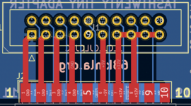
You know, this possibility had not occurred to me; I had just assumed - and that's often my downfall, lol. After opening the PCB in KiCad, though, it looks like there shouldn't be an issue (to my eyes, at least). I took screenshots of the IDC connectors, and the pinout seems to line up with what's expected. Maybe it's because it's 1:00 AM, but, am I (very, extremely likely) missing something obvious? I know pin 20 on the IDC should go to pin 10 on the D-Sub (which is not connected here), but other than that I'm unsure why the HD20's interface cable couldn't just connect straight into the new PCB. Is there something I'm overlooking? 😥

Also, I'll probably dive in this weekend (or maybe one night this week) and see if I can whip up a drop in board. I would probably make it two PCBs: one for the rear interface and another tiny one for the LEDs that just connects via headers. A PCB the same size as the original controller board is probably a bit out of my budget at the moment, lol (no reason to not design one, though - it's not like it's really any extra work). My only concern is that the new design has two LEDs (one for power and another for activity) whereas the old controller just had one that was just on when powered up and pulsed when there was activity. Eh, I'll figure something out. Also, it just occurred to me - since there's no more need for the internal PSU, no IEC cable is required to drive this thing now!

Lastly, regarding the card slot: I wanted to do that very thing but, alas, full size SD cards are ever so slightly too thick to fit between the vents. 😭 A micro SD would fit, but the vents are probably too deep to access it easily. I'm also starting to develop symptoms of arthritis in my dominant (right) hand which, along with CTS and grip strength problems, is starting to make soldering very fine stuff (like a micro SD slot) rather difficult. I'll try to come up with something - maybe one PCB variant that has a DA-19 interface and another that foregoes that for an easy to access SD slot? Authenticity vs flexibility of use? And as far as a DA-19 connector goes, though, I've got a stack of battery-bombed IIsi and SE boards to harvest right-angle connectors off of, so I can thankfully avoid having to mess with the controller board in my dead HD20 (it's still good, it's just the Rodime that's toast).

Screen Shot 2022-03-31 at 12.57.09 AM.png

Screen Shot 2022-03-31 at 12.49.36 AM.png
 

tashtari

PIC Whisperer
it looks like there shouldn't be an issue
Actually, now that you mention it, I think you're right... but it's almost one in the morning for me, now, too, so my technical opinions are to be viewed with suspicion.
maybe one PCB variant that has a DA-19 interface and another that foregoes that for an easy to access SD slot?
Hah, I hadn't even thought of putting the SD slot where the DX-19 is. That's an excellent idea. That'd be the variety that I'd use, I think. I suppose it would preclude using a Floppy Emu, but I think I'd rather have the ability to swap an SD card out easily.
My only concern is that the new design has two LEDs (one for power and another for activity) whereas the old controller just had one that was just on when powered up and pulsed when there was activity.
You could maybe rig an LED with some glue logic such that it's on except when RD and !ENBL are both low. That'll give you a power LED that flickers on activity (the RD line will pulse low during activity in both directions), though it'll take some experimentation to find out whether it flickers enough - it might just end up dimming slightly.
 

demik

Well-known member
You know, this possibility had not occurred to me; I had just assumed - and that's often my downfall, lol. After opening the PCB in KiCad, though, it looks like there shouldn't be an issue (to my eyes, at least). I took screenshots of the IDC connectors, and the pinout seems to line up with what's expected. Maybe it's because it's 1:00 AM, but, am I (very, extremely likely) missing something obvious? I know pin 20 on the IDC should go to pin 10 on the D-Sub (which is not connected here), but other than that I'm unsure why the HD20's interface cable couldn't just connect straight into the new PCB. Is there something I'm overlooking? 😥

Also, I'll probably dive in this weekend (or maybe one night this week) and see if I can whip up a drop in board. I would probably make it two PCBs: one for the rear interface and another tiny one for the LEDs that just connects via headers. A PCB the same size as the original controller board is probably a bit out of my budget at the moment, lol (no reason to not design one, though - it's not like it's really any extra work). My only concern is that the new design has two LEDs (one for power and another for activity) whereas the old controller just had one that was just on when powered up and pulsed when there was activity. Eh, I'll figure something out. Also, it just occurred to me - since there's no more need for the internal PSU, no IEC cable is required to drive this thing now!

You could maybe rig an LED with some glue logic such that it's on except when RD and !ENBL are both low. That'll give you a power LED that flickers on activity (the RD line will pulse low during activity in both directions), though it'll take some experimentation to find out whether it flickers enough - it might just end up dimming slightly.

Pin 20 on the IDC (SPEED) isn't connected because it isn't used. Same goes for Pin 9 (-12V). So that may work although you may want to double check that none of the power lines are grounded.

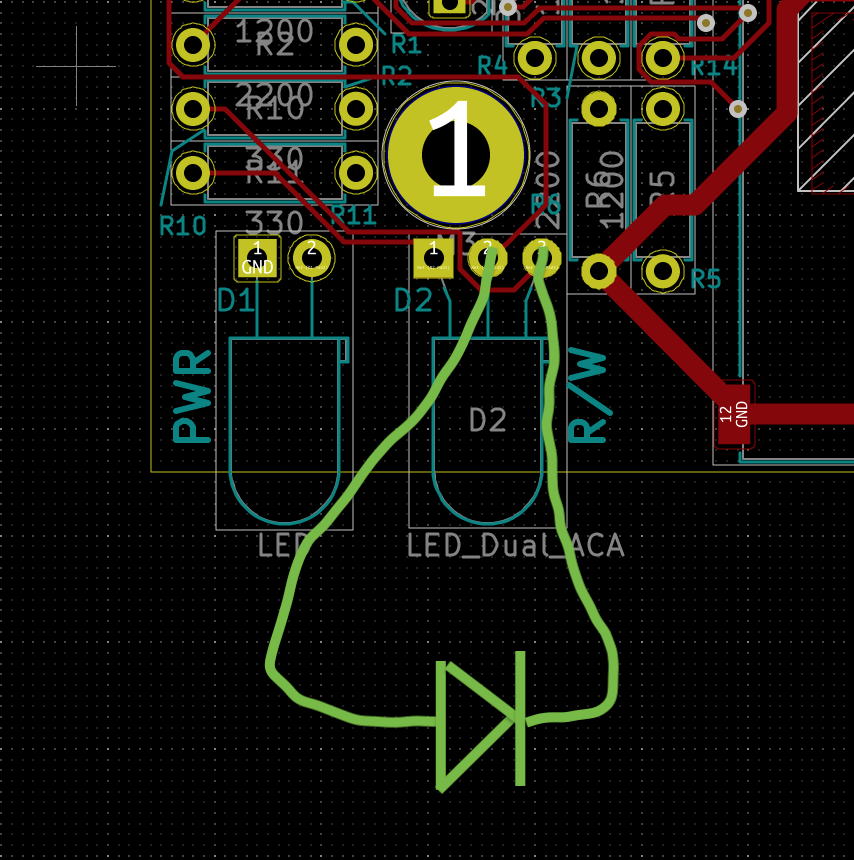
As for the LED, the logic is already there you just have to wire that differently. The LED circuit is a push-pull setup so just wire the read LED backwards as follow:

(Warning: extreme Paint.exe skill level)

TTT_HD20_inverse_LED.png


With that setup, assuming only one LED is used, the following components are not needed anymore:
  • R8
  • R11
Lowering R10 to 220Ω should help if you are using the original LED.
 
Last edited:

tashtari

PIC Whisperer
interesting factoid about the genuine HD20: when receiving data from the Mac on the WR pin, it echoes it back on the RD pin
Something else I totally failed to notice last night is that instead of resting high and doing a fall then a rise, in data mode, the RD pin idles low and does a rise then a fall. Both equally valid, since the IWM only cares about falling edges, but noteworthy.
 

warmech

Well-known member
@tashtari By any chance, would you happen to have a copy of the compiled firmware you could toss my way? I'm a bit unfamiliar with PIC programming (though I do have the resources to flash to IC) and I just want to compare my compiled version with a known good one.
 
Top