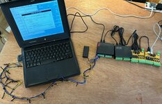
And also using an external power supply on Port A. I had some trouble with this, I don't understand why because it is working absolutely fine now, but before the chip wasn't getting high enough logic to drive its outputs. I'll try to understand it better.
View attachment VID_20221208_150621.mp4
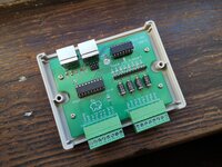
With this side you can even drive a small stepper motor - the chip is an array of transistors that switch the connection of each output to ground, so if you supply 12v to "clamp", then wire a bulb from 12v to PA1, you can swich the lamp by connecting and disconnecting it to/from ground. Only the ground is common with the rest of the circuit, but it is not as isolated as it would be with an optoisolator or a relay.
Until I used the software today I hadn't realised that Port A can be used as an input. I didn't account for this in my design because I just saw the relays and made an assumption. Thankfully, my board can still use these as inputs by bridging 1 to 18, 2 to 17, 3 to 16 and 4 to 15. The disadvantage of this is that there is no protection! No optoisolators and no TVS diodes! So this would be done at your own risk.
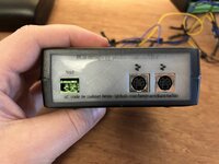
I'm happy with it as it is though. It will switch up to 50V at low current.
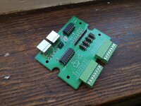
Oh curses! I just worked out a way to double the current it can handle! The datasheet for the chip says wire two channels in parallel to switch higher loads, I didn't think, I'm only using half of them, I could have just done that by routing them in pairs. The way they're arranged it would have been easy.
") and I clearly should have got the black smoked cases like
and I clearly should have got the black smoked cases like