• Updated 2023-07-12: Hello, Guest! Welcome back, and be sure to check out this follow-up post about our outage a week or so ago.

TashIO: Clone of BeeHive Technologies's ADB I/O

tashtari

PIC Whisperer
Designed some nice front & back inserts for the box.
Very nice! I'm hoping I can buy the requisite parts for this when all is said and done, I'd like to add it to my collection of Mac hardware that I had some part in creating...
 

Phipli

Well-known member
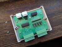
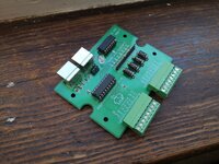
Got a chance to build mine today. Not tested yet.

I lazily reused the ADB port footprint that has too narrow side tabs and the TVS diodes were a tight fit, but otherwise things are looking OK.

If I do a rev 2 I'll stretch the board to putvthe ADB ports further out.

I haven't done the cutouts yet :) and I clearly should have got the black smoked cases like @aladds because yours looks amazing :)
 

Attachments

  • IMG_20221208_122948.jpg
    IMG_20221208_122948.jpg
    3.8 MB · Views: 33
  • IMG_20221208_122121.jpg
    IMG_20221208_122121.jpg
    3.9 MB · Views: 35

Phipli

Well-known member
And also using an external power supply on Port A. I had some trouble with this, I don't understand why because it is working absolutely fine now, but before the chip wasn't getting high enough logic to drive its outputs. I'll try to understand it better.


View attachment VID_20221208_150621.mp4

With this side you can even drive a small stepper motor - the chip is an array of transistors that switch the connection of each output to ground, so if you supply 12v to "clamp", then wire a bulb from 12v to PA1, you can swich the lamp by connecting and disconnecting it to/from ground. Only the ground is common with the rest of the circuit, but it is not as isolated as it would be with an optoisolator or a relay.

Until I used the software today I hadn't realised that Port A can be used as an input. I didn't account for this in my design because I just saw the relays and made an assumption. Thankfully, my board can still use these as inputs by bridging 1 to 18, 2 to 17, 3 to 16 and 4 to 15. The disadvantage of this is that there is no protection! No optoisolators and no TVS diodes! So this would be done at your own risk.

I'm happy with it as it is though. It will switch up to 50V at low current.

Oh curses! I just worked out a way to double the current it can handle! The datasheet for the chip says wire two channels in parallel to switch higher loads, I didn't think, I'm only using half of them, I could have just done that by routing them in pairs. The way they're arranged it would have been easy.
 

aladds

Well-known member
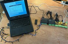
Just in time for the festive season 😊

Aside: if anyone else is considering doing something like this, don’t modify a set of Poundland lights, it took way too long. Just buy a few sets and accept that the colours will be mixed up! Or find a set with a controller and just replace that
 

Attachments

  • IMG_7734.MOV
    2.4 MB

Phipli

Well-known member
Just in time for the festive season 😊

Aside: if anyone else is considering doing something like this, don’t modify a set of Poundland lights, it took way too long. Just buy a few sets and accept that the colours will be mixed up! Or find a set with a controller and just replace that
Excellent. That it 100% the epitome of what retro computing is about.

Hats off. I meant to do something similar but I'm more easily distracted. Plus my house keeps breaking.
 

aladds

Well-known member
I also admit I've not done much lately, been distracted with other projects (and I was sick for a week!)

If people are interested in me putting together kits or having assembled boards available for them to purchase then I am certainly able to do something along those lines!
 

tashtari

PIC Whisperer
If people are interested in me putting together kits or having assembled boards available for them to purchase then I am certainly able to do something along those lines!
I'm definitely interested in one - preferably assembled, but would do a kit.
 

pfuentes69

Well-known member
I also admit I've not done much lately, been distracted with other projects (and I was sick for a week!)

If people are interested in me putting together kits or having assembled boards available for them to purchase then I am certainly able to do something along those lines!
Hello. I'd be very interested in a kit, but I'd prefer to know (approx.) the price. I'm in Europe.
 

aladds

Well-known member
Hello. I'd be very interested in a kit, but I'd prefer to know (approx.) the price. I'm in Europe.
Based on what it’s cost me to put together Scuznet kits, and the fact that this has a lower component count but longer construction time (plus some 3D printing for a nice case) I could probably do a fully assembled unit for somewhere in the region of £40 + shipping. EU would probably be relatively straightforward, at a guess postage would likely be between £10 and £15.
 

pfuentes69

Well-known member
Based on what it’s cost me to put together Scuznet kits, and the fact that this has a lower component count but longer construction time (plus some 3D printing for a nice case) I could probably do a fully assembled unit for somewhere in the region of £40 + shipping. EU would probably be relatively straightforward, at a guess postage would likely be between £10 and £15.
Would that include the case? If so that's pretty reasonable, although I'd still prefer a kit and assemble it myself... just to enjoy a bit more the project.
 

paws

Well-known member
Would this work on an ADB->USB adapter like an iMate? I realize that something that attaches directly to USB is probably more sensible, but I like the software support this seems to have.
 

Phipli

Well-known member
Would this work on an ADB->USB adapter like an iMate? I realize that something that attaches directly to USB is probably more sensible, but I like the software support this seems to have.
I'd recommend getting an RS232 Interface box. They're generally easy to control from any language and RS232 to USB adapters are cheap and common.
 

aladds

Well-known member
Would this work on an ADB->USB adapter like an iMate? I realize that something that attaches directly to USB is probably more sensible, but I like the software support this seems to have.
I would be very surprised if it doesn’t work, since the iMate supports software dongles and the like. But I don’t have one so I can’t say for sure!

As @Phipli says, though, a serial interface does help mitigate compatibility issues.
 

aladds

Well-known member
I’ve got a few boards working now. I can indeed set 4 of them to different IDs and control each one individually, as should be the case. Notably the AppleScript Scripting Extension used by RealBasic either isn’t being used correctly or has a bug, so that doesn’t work properly. But the HyperCard XCMDs are fine!

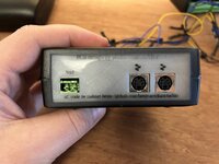
Also interesting was playing with toner transfer via. OHP sheets to make nice front and back plate labels. For a first attempt I think this came out pretty well!

Of course what this means is that I’m a step closer to having a few fully assembled and tested units for those interested 😊
 

Attachments

  • IMG_9344.jpeg
    IMG_9344.jpeg
    2.8 MB · Views: 25
  • IMG_9347.jpeg
    IMG_9347.jpeg
    2 MB · Views: 26

Phipli

Well-known member
I’ve got a few boards working now. I can indeed set 4 of them to different IDs and control each one individually, as should be the case. Notably the AppleScript Scripting Extension used by RealBasic either isn’t being used correctly or has a bug, so that doesn’t work properly. But the HyperCard XCMDs are fine!

Also interesting was playing with toner transfer via. OHP sheets to make nice front and back plate labels. For a first attempt I think this came out pretty well!

Of course what this means is that I’m a step closer to having a few fully assembled and tested units for those interested 😊
Hum, I think you can use XCMDs with RealBasic BTW.

What was happening with AppleScript? I've only messed with HyperCard.
 
Top