• Updated 2023-07-12: Hello, Guest! Welcome back, and be sure to check out this follow-up post about our outage a week or so ago.

TashIO: Clone of BeeHive Technologies's ADB I/O

tashtari

PIC Whisperer
Just a little Saturday project. Introducing: TashIO!

Elevator Pitch​

It's a clone of BeeHive Technologies's ADB I/O, a device with analog and digital I/Os for automation, control, and interfacing to sensors and other devices. It has existing software support in C, RealBASIC, Fourth Dimension, and HyperCard, to name just a few.

Project Status​

Firmware is nascent but feature-complete and passing tests.

Caveats​

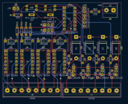
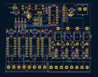
Somewhat more than my other projects, this really wants a full-blown PCB with relays, protection circuitry, &c., and this goes a bit beyond my skill set. Any volunteers?

Code​


Phipli

Well-known member
PIC16F1704 is what the firmware targets. If you can't get them, it should be easy to adapt to the PIC16F1708, maybe to the PIC16F1825 too, though I haven't tried...
Cheers. I've ordered some 16F1704 "risks" from China, and I'll try back ordering some domestically from a proper retailer.

I have some 4 pin mini dins somewhere. I'll see if I can breadboard something to start.
 

aladds

Well-known member
This is so cool!! I've started designing something in KiCAD, which based on the documentation linked above I believe to be somewhat correct. Need to check the Port A wiring so it supports opto isolators as an option and I don't have buffers on the Port B connections yet, but otherwise I think this is pretty good! :D

Edit: So other than mising a GND connection on Port B I think this might be as close as we can get to "original" since adding buffers to Port B means it can't be used for analogue inputs. Still need to add opto support to Port A, though

sch1.png
 

Phipli

Well-known member
This is so cool!! I've started designing something in KiCAD, which based on the documentation linked above I believe to be somewhat correct. Need to check the Port A wiring so it supports opto isolators as an option and I don't have buffers on the Port B connections yet, but otherwise I think this is pretty good! :D

Edit: So other than mising a GND connection on Port B I think this might be as close as we can get to "original" since adding buffers to Port B means it can't be used for analogue inputs. Still need to add opto support to Port A, though

View attachment 48738
Excellent work!

Yeah I haven't gone through the docs but guessed sime of the pins would be straight from the MCU. I know you mentioned using SMD parts, but I strongly recommend socketing the PIC - it means it can be replaced easily if soneone burns out a bin. Maintainability is good.

I've used dip relays in the past and they're expensive, I'd consider open collector outputs with a transistor. Basically as useful but much cheaper. What was the part? ULN2003?

Are there any PWM outputs in the original design?
 

aladds

Well-known member
OK, bar an ICSP header and a few numbering omissions, this is complete. Amazingly large bits of the schematics are in the appendix to the manual, which of course I only managed to work out after doing my first pass :)

I can only seem to get DIP parts at the moment, so no worries there! Even equivalent TVS diodes are still available. The original relays aren't made

Now on the the PCB design!


image.png
 

aladds

Well-known member
I've used dip relays in the past and they're expensive, I'd consider open collector outputs with a transistor. Basically as useful but much cheaper. What was the part? ULN2003?
I shall take a look at this as an option, but for now it's allowing for PRMA 1A05, PRMA1B05 and LDA101 DIP-package parts. These are an NO relay, NC relay and Optoisolator respectively. The 1A05s seem readily available on AliExpress, and I'm sure we can find other parts with the same pinout, but if not I can also include alternative sockets.

I'll make all the designs open source in time, too, btw. I don't want this to be lost to time again!
 

tashtari

PIC Whisperer
I've started designing something in KiCAD
Cool! This is exciting, I'm looking forward to seeing this realized.
I'll make all the designs open source in time, too, btw. I don't want this to be lost to time again!
You can use the TashIO github repo if you want to, to keep everything together, I put the PIC firmware in a subdirectory called "firmware" with the idea there could be a "pcb" subdirectory as well.
 

tashtari

PIC Whisperer
I was just going to say, it'd be great if this could fit in a premade enclosure. @demik used a Hammond case to great effect in his design for TashTwenty - with PCBs for the front and back panels, it looks really slick and professional.
 

Melkhior

Well-known member
@tashtari Darn, I didn't see before posting my take on TD.

@aladds On my side, I've added decoupling capacitors for the PIC, as I'm not sure what will happen to that wimpy ADB 5V supply when relays are engaged. Also I'm not sure if the PIC is designed to feed the LED directly, so I added a current-limiting resistor in my version.
 

Phipli

Well-known member
I'd consider a polyfuse on the ADB port 5v, possibly data, to protect other devices too.
 

aladds

Well-known member
First PCB version. Good shout on the LED resistor (added), polyfuse and capacitors, I'll add those.

I'll also likely add flood zones for 5v/GND - whilst the ADC isn't going to be RF frequencies, it's still worthwhile.

I've designed the board to fit in a Hammond RM2005LTBK, 84x68mm. I've not added the mounting holes yet so it'll likely need a revision to sort those out too.
 

Attachments

  • image(1).png
    image(1).png
    144.6 KB · Views: 12

Phipli

Well-known member
@tashtari

Is there meant to be a pull-up on the data line? There was on the TMK ADB / USB circuit. Are you using a pull-up on the PIC, or is it not actually needed. It seems an odd thing to need because if every device had one the pull-up would get stronger with every extra device.

TMK circuit :


aladds

Well-known member
Ok I've made those changes and here's the latest version. I've also uploaded the files from KiCAD if anyone wants to check my work! I realise I've still forgotten to add the mounting holes so I'll play with that later on. I think practically it's best to just have two (closer to the rear) mounting holes at this stage.

w.r.t pullups, I agree that it's probably best not to add one since other devices might have them too. (But willing to listen to other ideas here too)

Also considering if we should perhaps use an external 5v supply rather than relying on the ADB supply? Thoughts, comments welcome.

And I'll submit a PR for the github repo at some point soon too.
 

Attachments

  • image(2).png
    image(2).png
    150.8 KB · Views: 10
  • WaspIO.zip
    1 MB · Views: 1

Phipli

Well-known member
Ok I've made those changes and here's the latest version. I've also uploaded the files from KiCAD if anyone wants to check my work! I realise I've still forgotten to add the mounting holes so I'll play with that later on. I think practically it's best to just have two (closer to the rear) mounting holes at this stage.

w.r.t pullups, I agree that it's probably best not to add one since other devices might have them too. (But willing to listen to other ideas here too)

Also considering if we should perhaps use an external 5v supply rather than relying on the ADB supply? Thoughts, comments welcome.

And I'll submit a PR for the github repo at some point soon too.
Based on what I'm reading, I recommend putting the footprint for a pullup in the design. We can always not fit it if we don't need it, but it seems with long ADB cables, especially curled ones, you sometimes nees a stronger pullup than MCUs can provide.

I'll check your schematic tomorrow when I'm sober!
 

tashtari

PIC Whisperer
A lot happened here while I was not paying attention. =D

Is there meant to be a pull-up on the data line?
I have not used one in my testing, but I'm just breadboarding, so I don't know whether that's anything to go on. I didn't think they were necessary, though, because the ADB is open-drain, but I'm not an EE...

here's the latest version.
Cool! I love that this has gone from concept to execution and almost to manufacturing in one weekend.
 

Phipli

Well-known member
A lot happened here while I was not paying attention. =D


I have not used one in my testing, but I'm just breadboarding, so I don't know whether that's anything to go on. I didn't think they were necessary, though, because the ADB is open-drain, but I'm not an EE...


Cool! I love that this has gone from concept to execution and almost to manufacturing in one weekend.
I did a bit more digging, the Microchip ADB Application Note shows a pull up resistor too. I think its advisable to include one in ADB designs. It might only cause issues with long cables or specific setups.

Screenshot_20221113_210452.jpg
 
Top