• Updated 2023-07-12: Hello, Guest! Welcome back, and be sure to check out this follow-up post about our outage a week or so ago.

TashIO: Clone of BeeHive Technologies's ADB I/O

aladds

Well-known member
That’s incredible! Where were you last year? 😝

Seriously though this is awesome. Really impressed and looking forward to all the cool stuff we can do with these!

Edit: for what it’s worth I was inspired by @tashtari’s plea for ADB pheripherals so I went on a new rabbit hole of searching last week which found reference to MacTech magazine (which is awesome btw, and lots of back issues on Archive.org) which gave my the bzzzzzz website address. From there I was able to download the (corrupt) software archive from the. Way back machine with sufficient good content to get to where we are now!

Edit 2: do you have a complete, non-corrupt archive?
 
Last edited:

keelan

Member
Last year I was down a different ADHD rabbit hole and I was reverse engineering Trimble GPS receivers!

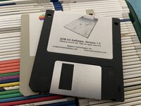
Software: I have an original floppy somewhere... I should look for it. The wayback machine appears to be struggling tonight, so I can't re-download the files, but when I did a couple weeks ago, while I did get a warning the archive seemed intact. I'll see if I can find that floppy.

For some of the software on the ADB I/O download page, I still have the source, because it's my software!
 

Phipli

Well-known member
When it rains, it pours!

So, in the course of four days, not one, but two ADB I/O clones were created, evidently without knowlege of each other's existence until now; one is complete (@keelan 's example), and one is in progress (the collaborative effort between @tashtari , @Phipli , @aladds and @Melkhior ).
Oh its worse, I started a "theme and variations" board last night. Similar but different. You might say there is a swarm of versions.
 

pfuentes69

Well-known member
Well... Now I'm just triply excited... If someone decides to put together a kit with a pre-programmed PIC, I'd be very interested
 

Phipli

Well-known member
@aladds

One more thing - don't forget to check the heights of the ADB ports and terminals. Given the height of the mounting posts, are they clear of the enclosure lid and do they align with the ends ok?

Edit - I just checked on an RM2015S enclosure and heights are fine on that. if your enclosure is the same height-wise you'll be fine.
 
Last edited:

Melkhior

Well-known member
@Phipli RM2015S is a bit large for my taste, I'm using the RM2005L dimension - but I've switched to mostly-SMD components to save space. But I haven't found 'clean' way to replace the socket-switchable relays/opto, those sockets take a lot of space.
 

Phipli

Well-known member
@Phipli RM2015S is a bit large for my taste, I'm using the RM2005L dimension - but I've switched to mostly-SMD components to save space. But I haven't found 'clean' way to replace the socket-switchable relays/opto, those sockets take a lot of space.
Yeah, I realise you're using a smaller box - I just have a 2015S sat on the desk next to me so it was a useful physical test with a 4 pin DIN socket I had too :)

The size and cost of DIP relays is why I'm interested in using a darlington pair array instead. The array isn't quite as flexible, but takes up quarter of the space. I'm also considering whether @tashtari might be willing to switch the Port A outputs to be a clock, data and set signal (one fewer pin) for a 74595 shift register. My darlington pair array has 4 spare pins, so it could be feasible to get the outputs from a shift register to increase the number of outputs. Also, the potential to add an output port that allows you to chain more shift registers to expand the number of outputs cheaply.

But... I want to do a code compatible version first before I add features. Even if the 4 unused channels on the ULN2803 are sat there glaring at me :)
 

Phipli

Well-known member
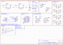
I haven't gone through it with a fine tooth comb, but this is my first pass at a schematic that replaces the relays with open collector outputs. It should be ok for a maximum of 50V and 500mA (not at the same time) per output (see datasheet, this is the maximum, but you are limited to a maximum 1W per output, and a total of 2.25W, so you'd only get 500mA at 2V. At 5V it is a maximum of 200mA per output and you can't drive all four that hard. 100mA per output at 5V is feasible) - not relay performance, but if we want more current we can replace the ULN2803 with four discrete transistors with a higher rating.

1668519249092.png

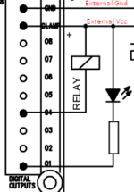
You need to collect a single external supply to the "Clamp" and ground connections, then any device you want to drive, you collect its +ve to the same external supply, and its negative to the output pin on the ADB board. Switching the outputs connects your device to ground, completing the circuit and powering it on. This is an example of how you'd connect an LED and a relay to my Port A (note this doesn't match my pinout, I'm just talking about how the circuit works) :

1668517263593.png

Edit : I've clarified the text above and tweaked a couple of things in the drawing while I have time left to edit.
 
Last edited:

Melkhior

Well-known member
The size and cost of DIP relays is why I'm interested in using a darlington pair array instead (...)
Hehe, yes between @keelan and @aladds I think the 'pure/close replica' aspect is already well-covered. Mostly as an intellectual exercise, I'm looking at a 'modern' take, such as replacing the jumpers by SPDT switches (such as 204-121LPST and 204-122LPST).

I don't really have use for such an ADB toy, but it might be a useful tool to debug a home-grown ADB controller (perhaps even by getting rid of all the relays & stuff and just using Leds/switchs as I/O).

@tashtari During all your ADB work, did you investigate/figure out if it was possible to register an additional ADB controller ? I wonder how difficult it would be to implement one in the NuBusFPGA (and it's literally just one pin...).
 

tashtari

PIC Whisperer
Wow, awoke to the news of @keelan 's project - guess it just goes to show how much creative energy there is in this community. =)

I'm also considering whether @tashtari might be willing to switch the Port A outputs to be a clock, data and set signal (one fewer pin) for a 74595 shift register.
I'm willing to cook up such a variation on the firmware, but how do you intend to deal with the fact that all the existing software for the ADB I/O expects that Port A will have four pins rather than eight?

I don't really have use for such an ADB toy, but it might be a useful tool to debug a home-grown ADB controller
You might check out my ADB test device and ADB protocol analyzer for that purpose, the latter converts any ADB traffic going by to a UART, the former emulates two host-controlled ADB devices, both would be very useful in testing out an ADB host.

During all your ADB work, did you investigate/figure out if it was possible to register an additional ADB controller ?
ADB is supposed to have only one controller, and based on what I know about the Mac SE controller firmware, I doubt it would be a good idea to try and have two - the controller expects to be able to transmit whenever it wants to because devices only transmit in response to its Talk commands and the bus can be assumed to be free the rest of the time - and most of the time, it's hammering the bus with a Talk 0 command for the last device it talked to, so there's not much time to get a word in edgewise. Maybe, if you really wanted to, you could time your secondary controller's requests so they came in halfway between Talk 0 commands from the main controller, but it's risky because the controller can start a command at any time...
 

tashtari

PIC Whisperer
how do you intend to deal with the fact that all the existing software for the ADB I/O expects that Port A will have four pins rather than eight?
Thinking on this more... it would require a not-insignificant respin of the firmware, but I could retarget this to a bigger PIC like the PIC16F1708 and have each chip imitate two ADB I/Os (since the software is designed to handle up to four on the same bus) and that way double both ports to have eight pins instead of four. Hmm...
 

tashtari

PIC Whisperer
Hell, why stop there? I have some PIC16F1788s on hand that don't have a slated purpose yet, I could make it imitate all four units and quadruple Port A. Wouldn't have enough pins to have more than one Port B, but I could make the other three Port Bs act as controls for the SPI/I2C peripheral or something cool like that...
 

Phipli

Well-known member
I'm willing to cook up such a variation on the firmware, but how do you intend to deal with the fact that all the existing software for the ADB I/O expects that Port A will have four pins rather than eight?
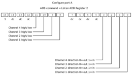
I was thinking maintain compatibility for the existing four outputs, but extending the protocol to recognise extra variations using the "don't care" bits in the ADB commands?
1668524733968.png
They wouldn't be "don't care" any more, an if you were using software written for the original you'd have to not connect anything to them because the behaviour wouldn't be predictable, but if I'm not being daft... it should be possible? To use them, you'd have to modify the original computer side libraries to send the extra bits.
Given bit 15 seems to be always 1, I think you'd only get 3 more outputs, instead of the 4 I hoped for. For "control individual channels" you could add an extra bit to the channel indication (bit 10) and it would work with 8 outputs, or even more if you used bits 10 through 13.

1668524962200.png

Feel free to tell me I'm being an idiot :)
 

Phipli

Well-known member
Thinking on this more... it would require a not-insignificant respin of the firmware, but I could retarget this to a bigger PIC like the PIC16F1708 and have each chip imitate two ADB I/Os (since the software is designed to handle up to four on the same bus) and that way double both ports to have eight pins instead of four. Hmm...
Actually, there are spare bits next to the channel select bits - you could potentially add an extra data bit there (instead of always 1, send a zero), and have that represent a second bank of outputs on Port A as a "virtual" box? There seem to be spare bits for send and read, next to the channel bits.

That wouldn't consume the jumper ids and would let you still chain devices.
 

tashtari

PIC Whisperer
I thought of repurposing the don't-cares, but I don't like what that'd do to compatibility with existing software. You wouldn't be able to add a third bit to the channel select bits in the form of Listen 2 where the MSB is 0 because you wouldn't be able to know what that bit would be in legacy software. Adding three more bits to the form of Listen 2 where the MSB is 1 would be harmless, but you'd lose the ability to change the I/Os with a timer, plus I don't know if every Mac-side implementation uses that form of Listen 2 to change the I/Os on port A. Using the multi-unit capability and compressing multiple units into one feels a lot safer and cleaner to me. Do you have an application in mind that would require so many I/Os that it'd need four chained devices with 12 I/Os each?
 

Phipli

Well-known member
I thought of repurposing the don't-cares, but I don't like what that'd do to compatibility with existing software. You wouldn't be able to add a third bit to the channel select bits in the form of Listen 2 where the MSB is 0 because you wouldn't be able to know what that bit would be in legacy software. Adding three more bits to the form of Listen 2 where the MSB is 1 would be harmless, but you'd lose the ability to change the I/Os with a timer, plus I don't know if every Mac-side implementation uses that form of Listen 2 to change the I/Os on port A. Using the multi-unit capability and compressing multiple units into one feels a lot safer and cleaner to me. Do you have an application in mind that would require so many I/Os that it'd need four chained devices with 12 I/Os each?
I don't have an application in mind, just room on the PCB and the fact that you can run a shift register from 3 pins and we had four. We could use the 4th remaining pin to connect a "compatibility mode" jumper but...

Don't worry about it - lets get some working boards with the existing software. I'm just thinking too loudly.
 

tashtari

PIC Whisperer
I just pushed a change to the TashIO repo that should make it compatible with the cheaper PIC16F1703 with only minimal changes (the assembler directive and the header #include). Haven't tested this myself, though, as I don't have any 1703s on hand and they aren't compatible with MPLAB 8 anyway... but hopefully this change will make life slightly easier in this seemingly-never-ending chip shortage.
 

Melkhior

Well-known member
ADB is supposed to have only one controller
Sorry, I wasn't clear; I didn't mean a second controller on the same ADB bus, but a second controller in the Macintosh that would create a second, independent ADB bus, so you could have more devices.

Now that I think about it, I could probably just try to add an ADB controller in the SBusFPGA instead, as I have a lot more control over NetBSD as an OS.
 
Top