@aladds, excellent work and I'm not quite sure how you did it quite so quickly. Its taken me far to long to go through what you've done. Anyhow, I've gone through your KiCAD files, really sorry if I've misread anything or made any mistakes, and I'm not certain I've caught everything. I've not commented on style or anything like that, but at a high level, it is worth avoiding tight corners in traces (90 degrees, or funny corners at pads). It can simplify and improve circuits to flood almost an entire side with a ground plain, and you could do with some much wider traces where decent power is being moved about (the power rails and the relay outputs, plus the protection circuitry (diodes on the coils and the TVS diodes)). Lastly, some of your power traces are extremely meandering and travel a long way from the source through thin wires - if these are loaded at the far end you'll likely see voltage drops.
@tashtari did you confirm what pins are mapped to what function? Sorry if I missed it. I'm just aware the original manual calls everything Port A and Port B, but the PIC we're using doesn't have a Port B
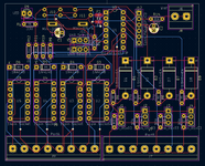
") Comments on WaspIO
Comments on WaspIO
Power traces need to be thicker. From ADB, to the PIC and elsewhere, or shorter.
Traces between the screw terminals and relays need to be significantly thicker. They need to handle a decent amount of current, for example if the user is switching a motor with the relay. Same with the TVS diodes.
ADB sockets are facing into the board I think. Also, if the part mentioned on the forum is to be used, you are missing a couple of the holes for mounting tabs? There are three tabs on the "Lumberg" part. The following is from an old design I did (purple is the board edge) :

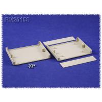
I recommend overhanging the front of the ADB port over the edge of the board by a few mm so that it is flush, or closer to flush with the enclosure end cap.
C1 is upstream of your pollyfuse.
A ground plain would be be good.
Pin 6 of the relay is not connected to anything that completes the circuit and so wont activate.

R9, R10, R11, R12 seem to be 1k resistors, when the manual shows 10k.
The MCU pins used for driving the relays don’t seem to align with the manual? It says PortA 1...4, but you’ve used PortC 3, PortC 2, PortC 1 and PortC 0. The manual’s Port B is connected to… RA4, RA2, RA0, RA1 rather than PortB 1...4. These might not be critical, but need confirming with tashtari. I haven’t checked that the required functions (e.g. analogue input) are available on the selected pins – did you consider this?
J7 screw terminal block – the Gnd pins aren’t connected to anything other than each other.

I would increase the resistance of the LED’s current limiting resistor, modern LEDs are stupidly bright. 1k is probably a better value, if not higher.
For the capacitors, I would put a single 100uF capacitor paired with a 100nF capacitor next to the ADB ports on the power rails, and then put a 100nF capacitor next to the PIC.