• Updated 2023-07-12: Hello, Guest! Welcome back, and be sure to check out this follow-up post about our outage a week or so ago.

SE/30 Jailhouse vertical bars and other issues

caver01

Well-known member
I am restoring an SE/30. Before posting, I have browsed the forums and read many similar accounts. The main theme so far is “recap” first and foremost, followed by cleanup, patience, perseverance and hopefully, kind collaboration.

SO, one issue at a time and some background info: This is late-model 1991 SE/30 with 8 megs of RAM, all SIMM slots populated. It has an intact, working lithium battery, and was discovered to have leaked electrolytic capacitors. It boots, has a working floppy and what looks like maybe an 80-meg SCSI HDD. System 7.x.

Initial problems:

Electrolyte around all of the sliver caps — NOW REPLACED. (before I even booted the system, I re-capped the logic board, cleaned everything in soapy water, isopropyl alcohol, dried. 

Now recapped and cleaned:

1. Booted without a chime, just a mild speaker pop.

2. Booted fine, though screen a little bit “shimmery” with a few rows of pixles shifting right a pixel-wdith ever few moments here and there. This is difficult to see, and it seems to settle down as it warms up a bit.

3. Attempts to play alert sounds result in abbreviated playback followed by a freeze. Cmd-Opt-ESC lets me force quit and relaunch Finder. Basically, audio triggers usually lock the application. This has evolved over a week or so. At one point, it was letting me play every alert except Simple Beep, which froze the system. Later, it let me play other sounds three times in a row, but by the third time, it would freeze. I have NEVER heard a boot chime. I once removed all SIMMS, and it plays a steady continuous chord.

4. Avoiding the sound issues, I have been able to load floppies, connect to the MacIPpi Gateway via AppleTalk (phoneNet, AsanteTalk bridge, ethernet, pi).

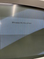
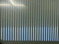
5. Finally, while transferring files successfully via AppleTalk, the screen flickered a second and BAM, I have “Jailhouse Mac”. Vertical bars are now obscuring the entire screen every eighth inch or so—three pixels on, four or five black—column after column.

I know I have a long way to go—awaiting shipment of desoldering alloy to remove some chips. I was intending to follow @PotatoFi’s recent example by removing the ASC and cleaning pads etc. as our audio issues are/were identical. But the jailhouse vertical bars are a setback. The system still boots fine, it still works on the network without issue—I just cannot read stuff!

SO, I am posting a picture of the screen and asking for some input. Where should I start? I assume this is probably corrosion issues around the caps I replaced. I have read other examples here where advice is given to buzz traces. I can start with some of this now as I have a meter, but what is my best reference? Should I be using the Apple schems from the MacintoshRepository.org or is there a better reference list of point-to-point continuity tests I should use? I have seen reference to traces A(0) and A(1) for example, but what are these? Should I spend some time learning to read the schematics? Am I seeing this referenced as lines from the ROM SIMM?

Any sage advice is welcome, as I have all the time I need (great stuff for lockdown, eh?) and naturally hoping to learn a ton. I am not afraid to do replace stuff, as I think I did a fine job on the caps. I have a decent iron, solder, flux, wick, loupe. No reflow station or heat or anything too advanced. . . and I await some de-soldering alloy.

This could go in several directions (and probably will) but it is the video issue that has me posting this here now. Is that a good place to start?

Thanks!
5BBC47C4-4514-4E3F-9A32-C36A98B102BB.jpeg

7F1811E0-9347-462B-966D-319EE6A2586E.jpeg

 
Last edited by a moderator:

cmelloni

New member
I have exactly the same problem on a Mac/30 after recapping. The machine was not working when I got it, so I'm not sure if the video was OK before the recap or not.

I don't have a solution yet, but I'm planning to (1) Re check the Video ROM and tracks even if the board is clean and in good condition, (2) test the motherboard on a different CRT. It's unlikely to be a faulty display, but just to eliminate the possibility (3) test the VRAMs. (4) Maybe J12 connector problem...

I will posted if I have some news.


Bolle

Well-known member
I would start by looking for a broken/intermittent address line somewhere between CPU and the ASC and video address muxes.

Had something similar happen before (crashes when playing certain sounds)

There is a via right under the ASC that goes bad when cap goo leaks underneath.

 
Last edited by a moderator:

caver01

Well-known member
ok, good advice for sure but part of my question is the practical aspect—HOW is this best accomplished? i assume continuity checks with a meter, but is there a good guide or reference i should use, or do we all use schematics?

 
Last edited by a moderator:

Bolle

Well-known member
Yep, just follow the schematics and buzz out the signals with a multimeter in continuity mode.

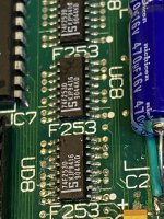
Check address lines (usually it’s A0, A1 or A2 involved with video issues) between the CPU and the video address muxes (UA8-UD8) as well as the ASC.


caver01

Well-known member
Thanks for adding experience to focus my efforts on the likely problem areas.

Another practical question. . . please forgive my ignorance, but I have seen you mention A0, A1, A2--are these references to pins from the CPU? If so, how do find them? I can see references on the schematics, but as this is my first foray into using them, just a little guidance could really set me to work. I understand chips with a little notch, or a dot, or the silkscreened dot on the board is often Pin 1, but I expect for the CPU this is somewhat different given the pin arrangement.

Is there a method I just don't know about? for instance, do you clip on a wire somewhere to make it easier to probe over and over? Maybe alligator onto tiny prob wires first to make it easier to touch the pins? I checked a few points when I re-capped the logic board that had me touching SMD resistors on the bottom--which was tricky because I was holding the board on edge, back to front probing etc. and maybe that's just the way it goes! I am willing to try, but where can I pickup A0 for example?

Thanks for helping the newbie!


Bolle

Well-known member
A0, A1, A2, and so on are the address lines. You have 32 of them.

When looking at the schematics you will see the signal name (let's take A0 for example) and the corresponding pin number (pin A2 in case of A0, pin C4 for A1, pin D13 for A2...)

When you flip pages to the video section you will see that A0 should be present at pin 4 of UD8 as well. Put your probes on pin A2 of the CPU and pin 4 of UD8 and you should get continuity between those two.

Repeat with all other address lines that are present in the video section but as said you usually have A0 or A1 broken because that's where the cap goo is getting most of the time:

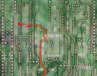
Bildschirmfoto 2020-09-21 um 08.40.06.png

The breaks usually occur where the traces enter the solder pads of the ASC or for A0 where the trace enters the solder pad of UD8.

Because you also have issues with your audio I would suspect the breaks to be where I put the little blue marker.

The big blue circle is where the cap goo usually spreads.

 
Last edited by a moderator:

caver01

Well-known member
OK! Thank you so much for taking the time with this, especially the image. I will try to match up what you are describing withe the schems and do some probing. i really appreciate the hand-holding and hope it pays off with another rescued SE/30. I am also feeling better about my decision to get the desoldering alloy so I can do a better job of cleanup around and under the ASC. More to come, I am sure, but this answers a lot.


caver01

Well-known member
Having printed an enlarged page from the Video section of the Apple schematics, I have started probing. Once you get the hang of it, I guess these drawings are not too hard to understand. One thing that threw me for a few minutes was the repeated references to the same ICs. It left me wondering “well which is it?” before I realized that they each feature mutually exclusive pins—so I concluded that this is an engineer’s technique to simplify the drawing by splitting the ICs in two in order to group similar function/logic making it easier read (and troubleshoot).

Armed with an image of the MC68030 pinout and a better understanding of how to translate the schematics, I checked the traces and pads shown above. At least these two buzz clean and both trace back to their respective CPU pins. I call that progress—both in my testing and my undertstanding.

I then probed around a bit, verifying my perception of the schematics and the different ICs (probing ground pins etc.), so I am off to a good start I think. I will be checking as many traces as I can from the video section starting with the address lines as suggested.

My desoldering alloy is not going to arrive until Friday, but I am concerned about how to address bad vias. I see plenty that are discolored—some of which I have cleaned and re-tinned as a result of cap replacement, but still concerned about shorts and intermittent connections under the ASC. More to come on that probably over next weekend, but probing traces will continue for the next few days.


caver01

Well-known member
One question that may make things go faster: are there some convenient vias where I can pickup address lines on the top side of the logic board? holding probes on the 030 pins is a balancing act. Now that I write this, I suppose I still need to do this at least to one spot if only to verify connections from the CPU, but if someone has a chart/image to easily verify front to back that might help.


smiba

Well-known member
Just to be sure, what did you replace the capacitors with?

The audio circuit exists out of a bunch of caps that often leak, so I assume you replaced them. If you replaced them with an inadequate replacement this may cause audio issues.

If the audio signal is affected, so may their working in different parts of the board.

I think the jailbars are a seperate issue from the audio though, just for us following along, any chance you could take some high resolution shots of the video / PAL areas? In my experience corrosion or damaged traces can sometimes be easily spotted on pictures, while they were hard to see with my own eyes

 
Last edited by a moderator:

caver01

Well-known member
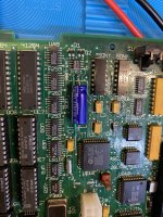
There’s a shot of that area.

I did have one trace pull up (watched it happen) alongside that through-hole which I fixed with a wire. You can see the green insulation. But video was working after that fix (and I had a nice tinned stretch to pickup that trace and connect it to the via above.

Thanks for reading along!

So far all of the address lines to CPU are testing good from UA8-UD8. Questions coming. . .

image.jpg


smiba

Well-known member
Can you check out UG6 and UF8A as well?

UG6 is responsible for the final video signal going to the CRT, although its quite possible (and likely) this fault happens at an earlier moment. I think its interesting that its just missing 2 pixels every 2 pixels though, as that is a pretty binary isuse (second digit staying low)

I'm not very well known to the video circuit as its complicated and abstract due to all the generic PAL chips, I may check it out a bit more tomorrow.

As for the audio check out C4's via on the negative side, it looks affected by the leaky caps. This via goes to R12 on the other side of the board, if you need a place to check for continuity.

If I can be honest the soldering on the caps look a bit sketchy in general, so I'd recommend just checking the connections to the capacitors. You may benefit from using (more?) flux to better guide the solder into position and prevent it from oxidising. When I work on boards that had leaky capacitors, I first replace the existing solder with new solder and then remove the new solder again with solder wick. This leaves a nicely tinned pad and reduces the chance of contaminants still being on the pad which help to bond them

 
Last edited by a moderator:

caver01

Well-known member
That via does look a bit dark. Thanks for the advice on more flux. That seems to be a consistent message everywhere in my research—flux flux flux! Haha. Ok, so the via tests ok through the board and to R12. Actually, all of the capacitor connections tested good following a nice diagram I found that lists all of their continuity check points—many being one end of a resistor on the negative side

of The board. I do wish my soldering was a bit cleaner, but I am getting better!

I guess a week or two has passed since the recap, so perhaps I need to retest and verify them, and maybe redo some. 

 
Last edited by a moderator:

caver01

Well-known member
Well, I got the hang of reading schematics really fast—nothing like just diving right in. I have now successfully buzzed ALL traces on page 5 (video) which includes UC6 UC7 UA8 UB8 UC8 UD8 UE6 UE7 UE8 UF8 UG6 UG7 UG8 UJ6 UK6, R16 R17 R18 R19 R23 and all address lines mentioned back to the CPU. I have not tested lines that lead off-page except for the address lines to the CPU.

All continuity tests were good. Where does that leave me? Shorts under the ASC or other chips that may be harboring electrolyte? A bad chip?

Without direct design knowledge, I am left to speculate, but it would make sense to me if I have a short that causes bits to stay black no matter what, repeating every 8 pixels or something. It does look like 3 pixels are fine, four black, three fine, four black and so on.

I thought about taking a screenshot, but it seems I cannot prevent it from triggering a sound, and because I have sound issues, this locks the machine before it can write a PICT image. Thought I might learn something by that image.

 
Last edited by a moderator:

caver01

Well-known member
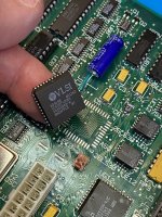
Given that I am also troubleshooting sound issues, I have removed the ASC chip using de-soldering alloy. This, along with appropriate cleanup was much easier than I expected it to be  and I would not hesitate to use the technique to replace other ICs (video muxer(s) perhaps? In any case, I printed page 7 of the schematics on tiled sheets of paper for reference and I will be doing continuity checks for the ASC. It will be a LOT easier to do that with the chip removed!

CBEBBB46-7BE3-431E-B9BC-B1B086AF6AFE.jpeg


caver01

Well-known member
New development for sound!

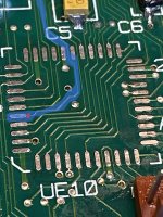
With the ASC removed, I started buzzing the lines from UE10 to various other components. I definitely found a problem: Pin 2 does NOT connect to Address line A(5)! I think I can see the failure point with the chip removed. Looks like corrosion of the trace right as it leaves the pad extending under the chip—probably broken right there. If I zoom in on that trace, it exits the area between pins 34 and 35 and heads past C5 to via between C3 and C2. That via tests positive to A(5) so I think I am looking at a broken trace right at the pad for Pin2.

Given a broken line to A(5), this might explain my sound issue. What is the recommended fix? Should I run a wire topside to that via after putting the ASC back on?

F16EC942-0106-4CA0-8D0F-E2A33EE6CBFF.jpeg

 
Last edited by a moderator:
Top