• Updated 2023-07-12: Hello, Guest! Welcome back, and be sure to check out this follow-up post about our outage a week or so ago.

Restoring a Lisa widget drive

mactjaap

Well-known member
I restored a widget drive to a certain point. See my old posting:


it it works on a “donor” external PSU. The problem is that it is very hard to start. To get it on I have to fiddle with the power on/off switch on the PSU. It helps if you spin the disk counter clockwise and then do the power trick. 

Some questions:

- What can I do to let it start more easy? Can I lubricate it? Or can I adjust the motor?

- I don’t have a power harness. Can I use some connections on the power supply or board?

- is there a better way to power switch the disk on with its external power unit? Should I use a kind of special switch?

- how to get the special power connector for the drive. Is it only for a widget or is it some kind of standard?

 
Last edited by a moderator:

MOS8_030

Well-known member
It may just need lubed or the original PS may have a "start-up" circuit or you may need a more robust 12v source.

You can still buy those Molex connectors.

Look for something like Molex 09-65-2068. (Well that's the header, you get the idea.)

There's a million Molex connector types, you have to search a bit to find the right one.

 
Last edited by a moderator:

mactjaap

Well-known member
Thanks for these answers! I tries to find a howto for lubrication of a widget. But I’m clueless. Could you tell me a good side or give advice?

i will try to tab from the Lisa itself. Only have to find out where all the currents are. 


MOS8_030

Well-known member
I have no advice about lubricating antique hard drives. I imagine that it would have to be done very carefully with an appropriate lubricant. :)


mactjaap

Well-known member
Some footage. 


Here you can see how it starts. 

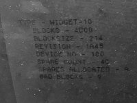
I also used used the BLU disk to do a check on the hard disk. Here are the results:

1A2E40E9-F797-48A9-8E1C-2650ACE8DBB0.jpeg

Not sure if this is good or bad. It seems that there are 9 bad blocks. Not sure if this is normal. Also not sure if it is wise to format the disk. 

 
Last edited by a moderator:

techknight

Well-known member
Bearing is toast. I can tell by the sound. You will need to replace it somehow. Its probably a sealed ball bearing assembly that can be pressed out when the drive is completely disassembled. 

You will probably need a sealed/clean tote with some gloves sticking inside it from the outside to do the work and disassemble everything, such as the platter and head stack assembly, and it can stay in the tote. Once you free up the housing with just the spindle motor, then you can take it out of the tote to do some actual physical work on it. 

If you can disassemble it by keeping the platter stack together as an assembly when breaking down the motor, that would be the recommendation. Otherwise, you will need a special tool very similar to a ring compressor to remove the platter stack so they dont slip and cause cylinder misalignment, otherwise it will need a true low level formatting again and that is only possible on a Stepper based drive. 

 
Last edited by a moderator:

mactjaap

Well-known member
Thanks for the advice technight.
I think I have to live with it as it is now I think. Such a disassembly sounds nerve-racking.

I hoped to get away with maybe some lubrication, but this is to much for me I think.


stepleton

Well-known member
it will need a true low level formatting again and that is only possible on a Stepper based drive. 
I'm not sure this is so for the Widget.

(as in, I'm literally not certain.)

Widget (which uses voice-coil actuation, not a stepper) doesn't use magnetic sensing alone to servo the heads. For coarse positioning, it employs an optical mechanism that scans a glass graticule mounted within the drive. (Word is that this same graticule is responsible for a common Widget failure mode: the glue affixing the glass to the drive fails, and the part winds up going somewhere it isn't meant to be. I assume that in the worst case this includes a bit of glass bouncing all over the inside of the drive housing.) Once roughly positioned onto the track, only then does the drive trim the head location by a small centering offset, which it accomplishes via some kind of magnetic sensing of the track itself.

It is possible to seek the heads without performing this fine correction---indeed, for low-level seeks, you have to order the correction on your own. Thus, you might imagine that you could format a completely degaussed platter by doing track-by-track coarse seeks and then formatting a track wherever the heads wind up. The fine offset adjustment should detect this placement and, after coarse seeks back to the track in the future, adjust the heads to the new location. Is this right? A true Widget expert I know (not an amateur like myself) seems to think this is so. I'm in no hurry to try for myself, though, because I also see text like this:

image.png

(PDF page 137 here)

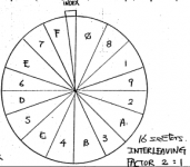
and diagrams like this:

image.png

(PDF page 8 here)

and I wonder whether the Format_Track command is really capable of initialising a track with that "servo data" and that index wedge. I am sure the expert I mentioned is aware of this information, though. I guess we'll find out over time, and who knows, even if the drive really can't format itself in its "stock" configuration, maybe it'll be possible to make a gizmo that interfaces directly with the heads and actuators at the lowest level and formats tracks with everything they need.

In the meantime, more information than you probably require for adjusting the optical servo mechanism can be found at the end of this document... unless you happen to be somebody called Walt Webber, who as the last page shows requires even more information.

 
Last edited by a moderator:

stepleton

Well-known member
Here is some more information, but probably not enough for old Walt. I remembered a diagram of the graticule from somewhere, and here it is in Figure 1 of this patent:

http://bitsavers.informatik.uni-stuttgart.de/pdf/apple/disk/widget/patents/4707754.pdf

On Page 10 you can also find a description of the mechanism, under the heading "Optics Scale".

(sorry @mactjaap, none of this is helping you fix this drive of yours, but I hope it's at least interesting :lisa2:  )


mactjaap

Well-known member
Found a Molex connector housing:

09-50-3081 -  Connector Housing, KK Series, Receptacle, 8 Ways, 3.96 mm

Not sure what kind of crimp connectors fits in...and how to do this im a simple way.


mactjaap

Well-known member
..... looked at the Lisa list and found this one 08-70-1030

More interesting stuff... I my setup pin 3 has 12 Volt....Maybe this is not OK.....

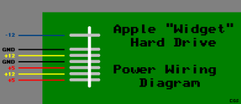
I've successfully powered a working Widget by following your advice. For anyone searching the archives, here is the Widget power connector pinout I used, as you would see if you were looking down onto the top of the Widget and the connector.
 
 
              +--------+
     <-----|   -12v | 8
            | No pin | 7
       <-----| Ground | 6
To   <-----|   +12v | 5
PSU  <-----| Ground | 4
                   | Pwr OK | 3
     <-----|   +12v | 2
     <-----|    +5v | 1
           +--------+
 
and as you can see, the Power OK pin is not connected. The connector I used was a Molex 09-50-1081 housing with 08-70-1030 crimp terminals (although Molex would seem to prefer to only sell those as packaged in 08-70-1031 now).


mactjaap

Well-known member
I have cut wire 3 and it is a no go. PIN 3 needs 5V. I used this used by CelGen to break out a Widget drive:


voeding.png


stepleton

Well-known member
I have cut wire 3 and it is a no go. PIN 3 needs 5V.
Opinion seems to be mixed about this. I too have a Widget that I'm trying to fix, and one of the mysteries involves this pin. I'm of the opinion that you shouldn't need to power it. Indeed, on my one widget that does work, you don't need to---it spins up just fine with nothing connected to that pin.

If you look at this schematic, you can learn more about what Pin 3 does. It doesn't look to me (note: a computer programmer by trade, not a hardware engineer :lisa2:  ) like it ought to be powered, but I think it makes sense that powering it would work around a potential problem.

By my interpretation, Pin 3 is a power sense pin that's meant to be fed back to the power supply. In a working widget, resistor R1 should pull this line up to near +5V. This line is one input to the AND gate in U11, and assuming the other input is also high (which it should be for a drive that isn't plugged into anything, thanks to the pull-up resistor R6), then the AND gate output (called POK) should also be high. People more familiar with Widget than me say that POK has to be high in order for the drive's microcontroller to start up.

The existence of R1 suggests that if Pin 3 can't reach +5V on its own (i.e. without external power as in CelGen's diagram), then something is wrong with the circuitry that generates the POK signal. But if that's the case, maybe supplying +5V there externally can "boost" the generation of POK. For instance, maybe U11 is going bad and is pulling the Pin 3 line low---if you look at the 74LS09 datasheet, the schematic for the AND gate inside U11 suggests that you would only need one diode inside to fail for that to happen. If you force pin 3 high with +5V from your PSU, then maybe you are unwittingly implementing a workaround to damage to U11.

Anyway, I don't think you really want to power Pin 3, and I'm going to try to fix my own broken Widget without doing that. But I'm still learning about this circuit, and I'll probably know better in a few months.

More on this particular mystery can be found on recent LisaList posts.


stepleton

Well-known member
An update:

I replaced U11 on my Widget controller board, and this has allowed the drive to operate again after about 20 years :lisa2:

This result keeps me feeling doubtful that Pin 3 of the Widget power connector ever needs to be powered on a properly functioning drive. Given the two reports on this forum of people needing to power this pin in order to run their Widget, I'm starting to wonder whether U11 just has a tendency to break from time to time.

--Tom


mactjaap

Well-known member
Did some testing and I think I have some kind of electrical problem. Could be on my external power. Could also be on the widget.Not sure yet. But I reconnect the external harness and now have stable power. And..... I now can confirm that Tom his theory is right. Pin 3 does not need to have 5V. I have the disk now working without the 5V on pin 3!

Also some footage. I now have a work around for 12v on pin 3.


Last edited by a moderator:

mactjaap

Well-known member
Did some more testing and a spontanius start of the disk is not good possible. I really have to give it a little push so it can spin. Could be that the bearings are so bad that the motor doesn't start without a push. It there is a way to improvide this without tottaly opening up te drive I would like to hear it. But I think for now I have to live with it.

 
Top