• Updated 2023-07-12: Hello, Guest! Welcome back, and be sure to check out this follow-up post about our outage a week or so ago.

PowerBook Duo Wifi Modem

sutekh

Well-known member
When I previously expressed interest in developing an ESP8266 wifi modem replacement for the Duo, @techknight correctly pointed out that the "modem" board on the Duo serves other purposes (e.g., the power switches) and the much larger connector isn't just a glorified RS-232 port. Furthermore, the Duo's Developer's Note is much more vague than it's 1xx companion and doesn't include connector pinout info. In short, building a replacement would require a fair amount of reverse engineering beyond the capability of this occasional hobbyist, so aside from buying a spare modem module from a recycler to play with, I tabled the idea.

Fast forward a couple months, I have a bunch of spare PB 1xx Global Village modems sitting loose as a result of an ongoing project to develop a wifi modem replacement for that series of laptops (thread over in hacks), and I happened to notice something: They use the exact same Rockwell chipset as my Duo 280c. Interesting... I know from experience I can get a PB 180 to speak AT to an ESP8266 serial wifi chip in place of the original Rockwell RCV144DPL equipped Global Village. I may not be able to easily design a complete Duo replacement modem board, but that doesn't mean I can't try to modify an existing one!

I lifted the Rockwell chip, grabbed the datasheet, took some measurements, and started plotting a course:
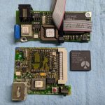
 

PXL_20201111_014332322.jpg

Here's what emerged a few hours later:
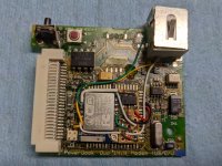
PXL_20201112_152836112.jpg

Pretty straightforward. Just an ESP-07 joined to a small piece of perf board containing a 3.3v regulator, a divider for RX, and a couple of pull-up resistors, all of which is double-stick tapped to the module. I repurposed the RJ-11 to make RX / TX / GND / GP0 externally accessible for the purpose of external testing and programming.

All in, it's no taller and has a slightly smaller footprint than the original chip. Here are the two side-by-side:
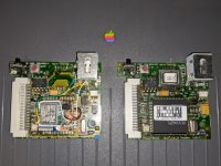
PXL_20201112_154939250.jpg

But, and it's a big but, it doesn't work... yet :) I can communicate with the ESP-07 using an FTDI to RJ-11 dongle I built, but when I try to open the port in MacTerm, it says the selected port is unavailable and power manager never supplies 5vdc. It's that last bit that I think is most telling. If power were being supplied, some logic from the now removed chip not being received, and then powered off in error, that'd be one thing, but the fact that it never even blips suggests to me that one or more of the pins needs to be connected to something or grounded. I'll keep pouring over the datasheet and metering it against the unmolested example...


sutekh

Well-known member
I’m guessing that the RJ-11 jack would be unusable after this modification? 


Usable for communicating with the ESP chip, yes. Usable for connecting to the PSTN via an analog phone line, very much no. Doing the later, with its 60-90vac, would cause very bad things to happen :)


Challenger 1983

Well-known member
Usable for communicating with the ESP chip, yes. Usable for connecting to the PSTN via an analog phone line, very much no. Doing the later, with its 60-90vac, would cause very bad things to happen :)
I figured, I forgot how much voltage phone lines carry  :p


sutekh

Well-known member
I’m thinking that the RJ-11 jack could be removed entirely and a blanking plate could be 3d printed for the port
I think you're overlooking the importance of being able to FTDI into the ESP8266. That unit is going to have to run an OSS package called esp_slip_router, and without the RJ-11, any updates or changes would require cracking open the Duo and connecting to it via an internal header. Plastics are fragile. Opening them infrequently is a good thing :)


Challenger 1983

Well-known member
I think you're overlooking the importance of being able to FTDI into the ESP8266. That unit is going to have to run an OSS package called esp_slip_router, and without the RJ-11, any updates or changes would require cracking open the Duo and connecting to it via an internal header. Plastics are fragile. Opening them infrequently is a good thing :)
That’s all very true I never thought of that, I guess I thought it wouldn’t need firmware updates or downloads 


techknight

Well-known member
The Duo uses a split serial system between that Rockwell chip and an ASIC thats on the logic board. I bet the ASIC needs to communicate to that rockwell chip before itll open itself up for communications. 

So what you need to do is emulate the communication protocol and initialization sequence of that rockwell chip, including all the GPIOs and their initial states, otherwise the Duo wont know what to do with it. 


Trash80toHP_Mini

NIGHT STALKER
Weren't all PowerBook modems "Soft Modems," relying on the main board's bits and CPU to do the heavy lifting?

Other thread? Interesting notion here, great fun to be had! But better I think to base a Duo NIC/WiFi solution on the power button card's available surface area, populating it with a SCSI based solution?

TLDR: Tangential Suggestion:

Almost twenty years ago l looked into an alternate approach to Duo 2300c/WiFi that would be compatible with the 68K variants I'd think. The PB1400's PCMCIA subsystem has the cage itself installed on a removable PCB daughtercard with TREX PCMCIA controller mounted underneath. Might custom ribbon cable/flexible PCB production options be available? Connect the underside solder cone/pins of the docking connector across the bottom of the Logic Board to the card cage PCB's connections in the HDD cubic? One slot for WiFi Card and one for CF card. Replace the external antenna with internal air-wires and none need be the wiser with unimplemented removable slot openings. Makes for an inexpensive solid state drive solution for SCSI limited Duos as well, though a plast-blasted 1400c needs give up the goods to do any of it.

Back to the earlier suggestion: Is it feasible to get much simpler Y adapter ribbon cables for connecting both HDD and SCSI NIC in the modem bay? There might need to be variations by model, whereas Docking connector to TREX PCMCIA cage might be a universal part?

edit: I've always had my suspicions that TREX was an off the shelf controller, though maybe Apple added some of the IR system's functions to it?

 
Last edited by a moderator:

sutekh

Well-known member
Weren't all PowerBook modems "Soft Modems," relying on the main board's bits and CPU to do the heavy lifting?
I don't think so, by virtue of that Rockwell modem ASIC, at least all five PB 1xx and Duo modems I own are true hardware modems. See, that's why I think what I'm seeking to accomplish here might be possible. Everything else notwithstanding (i.e., where the UART lives in the Duo, what else is included on the "modem" card, etc.), that chip has both an RXD and a TXD pin that I should be able to hijack for my own purposes. If this doesn't work or becomes odious for the reasons Techknight alluded to, I might just put the chip back on so it can provide whatever signalling it's expected to, but re-route the RX/TX pins to an off-board ESP8266.

Other thread? Interesting notion here, great fun to be had! But better I think to base a Duo NIC/WiFi solution on the power button card's available surface area, populating it with a SCSI based solution?
Yes, what I'm trying to accomplish here with the Duo is much easier with the PB 1xx series. Those modems have a 20-pin connector that's just a glorified RS-232 with a few modemy bits added. As outlined in the thread linked below, I've successfully devised a solution and gotten my PB 180 online using an ESP8266. OSH Park sent me a note this morning that my boards were finally back from fab and had shipped, so hoping to have a finished product there in the next few days!


A SCSI based solution would offer better throughput certainly, but would be way more complicated than what I'm after here. Just for starters, as you've alluded to, you'd need a custom ribbon cable to replace or to mod the board, as the modem is in the rear and the HD is up front. I'm paying close attention to the ongoing efforts of several forum members to develop combo SCSI ethernet & drive modules. Something like that could be remixed to fit in a 2.5" drive slot...

 
Last edited by a moderator:

Trash80toHP_Mini

NIGHT STALKER
I've been watching those combo SCSI developments closely as well, hoping for a PowerBook 100 solution.

____________________________________________________________________________________________

I'll drop the tangent at the end of this post. Sorry, you got me thinking, maybe someone might take interest in doing a parallel post or project. :?:

While SCSI is a big improvement over serial comms, the Duo family and the 1400 represent a special case.**** They've both got fairly ready internal access to the PBX bridged I/O bus. For all practical purposes it's a a full 68030 compatible PDS as defined in the Duo DevNotes. Such appears to be split at 16bit each in the case of the 1400's TREX daughtercard connector and Video/NIC Connector @25MHz. PBX bridged 68030 I/O bus is the full 32bit @22MHz on the Docking Connector of the Duo, your target machine. Prototyping can easily be patch wired to a Floppy MiniDock. Once a 1400 TREX card cage is up and running I'd suggest a PCMCIA/SCSI MicroDock marriage as was planned for the UltraDock form factor. Dunno, we'll see if anyone runs with the ball in Hacks, otherwise I'll try to work up a better development strategy for posting there.

****Not familiar enough with Blackird PDS expansion to add here, but it's an interesting topic for further research.

____________________________________________________________________________________________

I can't wait to see what you've done when you've played with the incoming boards, fascinating stuff. :approve:


sutekh

Well-known member
I made some progress here today. Turns out I had both software and hardware problems preventing the Franken-Modem from powering on.

The former was the result of not having the Express Modem drivers installed, without which, even though there's an option to select "internal modem", the Duo specific hardware isn't engaged. Certainly could have discovered this sooner if I'd bothered to test my unmolested original modem before starting! I thought I'd established a terminal connection to the internal express modem before, but clearly I'm confusing if with having done that on my 180c.

The latter was the result of connecting the ESP module to A vs. D power pads. From the Rockwell datasheet, A = analog, and D = digital, where the former is seemingly powered only under certain conditions.

Now, after selecting the internal express modem in my shiny new Express Modem cdev and opening the port in MacTerm, the ESP module lights up and I'm able to speak AT commands to... something. For a brief moment I hoped I was communicating to the ESP8266, but a few commands quickly disabused me of that notion. So, that brings me to techknight's comment below:
 

The Duo uses a split serial system between that Rockwell chip and an ASIC thats on the logic board.
I suspect I'm communicating with that ASIC (or some software layer), which must implement its own Hayes command set and then translate them to the modem's Rockwell chipset. I'd guess they built it this way to create consistency between what could be myriad hardware modem implementations (e.g., different internal modem revisions, the various Duo docking options, etc.)? Anyway, I'm sure this outcome was obvious to those who have more experience with the hardware, but I just had to touch the stove for myself  :)  When you said "split serial", techknight, I guess I was thinking the user or application entered AT commands would still reach the modem. Not so much...

Next step is probably to connect a logic analyzer to the RX pin and see if anything is reaching the ESP at the moment, and if so, what? If I can figure out what responses the ASIC / driver are expecting (likely by tapping pins on my original modem), I may be able to modify the esp_slip_router code to respond accordingly during initialization. It'd sure be nice if there was just an easy way to tell it to "bridge" vs. "route" though...  :/

 
Last edited by a moderator:

Trash80toHP_Mini

NIGHT STALKER
Dunno if this may help you here or for another developer's project? But you never know as the only stupid question  .  .  .

DuoDock and MiniDock both lack Ethernet and use the same modem (relay?) daughtercard. Wondering if re-purposing these docking connector lines to it might enable breaking 10bT or Wifi out to the docks?

143____ DAA CNTLF___Modem DAA control
144____ DAA ID IN_____ID input from 152-pin connector to Modem card
145____ /RING DET____Ring detect signal from the modem DAA
146____/RB DVR_______Modem relay B driver
147____/RA DVR_______Modem relay A driver

If nothing else, plenty of cubic is available for one of the larger multipurpose SCSI solutions for WiFi and SD card above the Logic Board or within the HDD bay of the DuoDock.


Challenger 1983

Well-known member
Dunno if this may help you here or for another developer's project? But you never know as the only stupid question  .  .  .

DuoDock and MiniDock both lack Ethernet and use the same modem (relay?) daughtercard. Wondering if re-purposing these docking connector lines to it might enable breaking 10bT or Wifi out to the docks?

143____ DAA CNTLF___Modem DAA control
144____ DAA ID IN_____ID input from 152-pin connector to Modem card
145____ /RING DET____Ring detect signal from the modem DAA
146____/RB DVR_______Modem relay B driver
147____/RA DVR_______Modem relay A driver

If nothing else, plenty of cubic is available for one of the larger multipurpose SCSI solutions for WiFi and SD card above the Logic Board or within the HDD bay of the DuoDock.
The duodock has its own optional modem card but as far as I know it works through the duo’s modem


sutekh

Well-known member
The duodock has its own optional modem card but as far as I know it works through the duo’s modem
Perhaps, but I'm not so sure. I think the full size and mini docks have their own modem hardware that allows for docked modem use even if the Duo connected doesn't have a modem installed. I'd have to crack open my minidock again to confirm, but I recall being surprised that it had what appeared to be a complete, modular internal modem of its own. That would make sense too considering that, ostensibly (at least according to the various period Global Village and Apple docs I've consumed), the internal modem was optional (although since it includes the power / reset buttons, there'd have to be something there, even if it isn't a modem per se). Perhaps someone else with more Duo experience than I have will weigh in...

This is what I was alluding to above though. I wonder if the reason they split the port and created this modem abstraction layer was to account for the fact that any particular Duo had to function seamlessly with any of several potential modems options. No end-user would have wanted to have to toggle settings, change drivers, etc. just because they connected to their Duo Dock at home or a Minidock at the office, right?

Anyway, I've gotta drag it back out to my bench and analyze the TX/RX pins. It could also be signalling on the Dx pins too, since it looks like the Rockwell's parallel interface can emulate a UART. I'd hoped I might be able to issue an ATO1 command to force the "modem" into data mode and start passing communication directly to the ESP without going through the dial / negotiation rigamarole, but no dice (just returns ERROR). Once I figure out what it's signalling, I'm hoping it's as straightforward as adding a little routine to esp_slip_router to look for an ATDx command and return a CONNECT to convince the Express Modem driver to enter data mode.

My PB 1xx boards are arriving Tuesday, so this project is probably going on the back burner for a bit...


Trash80toHP_Mini

NIGHT STALKER
Cool, can't wait to see what happens next in your other thread.

I've got three of these modem relay boards on the bench, one of which is from the disassembled MiniDock. Didn't look into it further yesterday, but my suspicion about it being a relay board was based upon lack of integrated logic. The single IC on the board is a decade counter: MM74HC. What's really interesting is that the Duo Modem looks to be operating outside standard Macintosh serial port configuration. Both Serial and Printer ports are implemented in the MiniDock and Dock while the internal Duo Modem remains operational? Could be or might not be, I'll have to go back to the docs to see if that's the case or if the serial port is disabled if the internal Modem is installed.

I'd thought you would be interested in the signals above. Relay card is labeled Internal DAA:

145____ /RING DET____Ring detect signal from the modem DAA

 
Last edited by a moderator:
Top