I finished recapping the display in my 180c the other day, with great success, and while I know there are capacitor lists for it out there, there didn't seem to be any references for suitable sizes/footprints for the replacements, so I thought I'd share my notes on what worked for me.
The caps I used are all slightly smaller than the original 'metal can' electrolytic footprints, but are still a good fit for the pads - given how tightly packed they are, I'm not sure how you'd be able to get a soldering iron in otherwise!
In hindsight, perhaps I should have bumped up the voltage rating on my replacement caps, given the various rules of thumb around voltage de-rating for tantalums, but I didn't think to measure what kind of voltages they were exposed to before I buttoned it all back up. I suppose time will tell - at least they're not going to leak corrosive goop all over the board if they fail!
Also, obligatory reminder: while metal-can style electrolytics have the negative terminal marked with a stripe, the convention for tantalums is to mark the POSITIVE terminal. Don't get them backwards (or rather, DO install them 'backwards' relative to the markings on the electrolytics, if that makes sense).
Before: Looking OK from the outside, but pretty disgusting underneath!
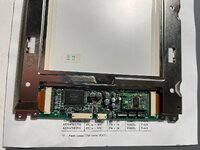
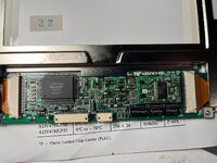
Make sure that you remove the metal bezel on the front of the display (bend the tabs that hold it on along the bottom edge, and gently pull it away), and carefully clean the other side of the circuit board too - the capacitor goo can migrate through vias in the board and damage the fragile and unrepairable flex cables connecting the control board to the LCD.
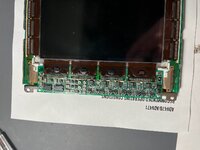
All cleaned up!
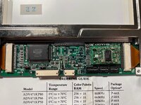
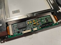
New capacitors installed. Note the small pieces of orange heat-resistant tape by some of the capacitors in the center - the capacitor goop had damaged the top solder-resist of the circuit board in a couple of places - you can see the exposed traces in the previous photo. From experience recapping my SE/30, it's *really* easy to accidentally bridge between the capacitor's pads and those exposed traces and end up with subtle faults that are a nightmare to track down, so the tape acts as an ugly-but-serviceable insulating layer to prevent that.
| Quantity | Value | Voltage | Original Footprint | Tantalum replacement footprint | Part |
| 4 | 47 μF | 16 V | 6mm diameter, 5.25mm tall | 2312 (6032 metric) | Kyocera TAJC476K016RNJ |
| 2 | 10 μF | 25 V | 5mm dia., 5.25mm tall | 1411 (3528 metric) | Kyocera TAJB106K025RNJ |
| 3 | 10 μF | 16 V | 3mm dia., 5.25mm tall | 1206 (3216 metric) | Kyocera TAJA106K016RNJ |
The caps I used are all slightly smaller than the original 'metal can' electrolytic footprints, but are still a good fit for the pads - given how tightly packed they are, I'm not sure how you'd be able to get a soldering iron in otherwise!
In hindsight, perhaps I should have bumped up the voltage rating on my replacement caps, given the various rules of thumb around voltage de-rating for tantalums, but I didn't think to measure what kind of voltages they were exposed to before I buttoned it all back up. I suppose time will tell - at least they're not going to leak corrosive goop all over the board if they fail!
Also, obligatory reminder: while metal-can style electrolytics have the negative terminal marked with a stripe, the convention for tantalums is to mark the POSITIVE terminal. Don't get them backwards (or rather, DO install them 'backwards' relative to the markings on the electrolytics, if that makes sense).
Before: Looking OK from the outside, but pretty disgusting underneath!


Make sure that you remove the metal bezel on the front of the display (bend the tabs that hold it on along the bottom edge, and gently pull it away), and carefully clean the other side of the circuit board too - the capacitor goo can migrate through vias in the board and damage the fragile and unrepairable flex cables connecting the control board to the LCD.

All cleaned up!

New capacitors installed. Note the small pieces of orange heat-resistant tape by some of the capacitors in the center - the capacitor goop had damaged the top solder-resist of the circuit board in a couple of places - you can see the exposed traces in the previous photo. From experience recapping my SE/30, it's *really* easy to accidentally bridge between the capacitor's pads and those exposed traces and end up with subtle faults that are a nightmare to track down, so the tape acts as an ugly-but-serviceable insulating layer to prevent that.

