• Updated 2023-07-12: Hello, Guest! Welcome back, and be sure to check out this follow-up post about our outage a week or so ago.

Portable - two steps forward one back

techknight

Well-known member
it should all be interconnected I believe. You should make sure all these lines all buzz out to each other, and back to the PMGR. you also need to monitor the voltage level on this line when resetting the PMGR and hitting a key. 


at0z

Well-known member
So P37 always showing 2.75v, when power first connected, during PMGR restart buttons held and after reset.

Trying a buzz out is interesting - the schematics for Q10,11,13 appear to show all three legs connected but on my board the middle leg is clipped in each case. No buzz on any pins. I did get a buzz on J21. So not sure if the schematic is "wrong" or I need more coffee...or both. But if I'm getting voltage on that pin, does that mean it doesn't matter ?


techknight

Well-known member
Yea, it doesnt matter. What I dont know is if that level is high enough. it may not be. I will have to dig through my notes and double-check. 

At this point all signs are either pointing to a bad PMGR IC, or SYS_PWR is open somewhere. 

 
Last edited by a moderator:

at0z

Well-known member
Yea, it doesnt matter. What I dont know is if that level is high enough. it may not be. I will have to dig through my notes and double-check. 

At this point all signs are either pointing to a bad PMGR IC, or SYS_PWR is open somewhere. 


Thank you! I can't quite figure out the source of the SYS_PWR river - if someone can point me in the right direction I could get some readings there and try a jump wire to the PMGR and see if that wakes it up..?


techknight

Well-known member
the PMGR controls SYS_PWR. you just need to make sure all points have continuity across the PCB back to the PMGR. 


at0z

Well-known member
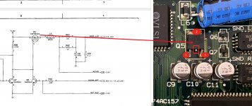
OK, some coffee onboard. Apologies if this is a dumb question but is this schematic to component mapping correct ?  I also understand my previous question was backwards now - the PMGR *is* the source...

Capto_Capture 2020-10-28_10-51-26_AM.jpg


desertrout

Well-known member
So P37 always showing 2.75v, when power first connected, during PMGR restart buttons held and after reset.

Trying a buzz out is interesting - the schematics for Q10,11,13 appear to show all three legs connected but on my board the middle leg is clipped in each case. No buzz on any pins. I did get a buzz on J21. So not sure if the schematic is "wrong" or I need more coffee...or both. But if I'm getting voltage on that pin, does that mean it doesn't matter ?
FYI, on those transistors, the drain connected to the board is on the 'top' side, opposite the pins.


at0z

Well-known member
I knew I should have added the disclaimer "this was a before shot for example use only".

But I did screw up my pin numbering on the PMGR chip so the ACTUAL reading on pin 37 is a more healthy (?) 5.17v and from there to the major players (GLUs and VIDEO and edge connectors and Q10/11/12) we do ring out. So at least it appears the roads are open.

Now I don't know if it was a trick of the light, but I thought I saw out the corner of my eye a flicker on the power draw from the lab supply at random, sometimes I think up to 400mA. Of course if I stare at it, it doesn't happen. I'll do some exploring of the board with my fingers, maybe something is a dry joint...


techknight

Well-known member
SYS_PWR has to be pulled to 0v for the system to come up. This is the responsibility of the PMGR. 

Chances are, the PMGR is bad. ive used up all my spare PMGRs on parts boards, thats how often they go bad. 


desertrout

Well-known member
SYS_PWR has to be pulled to 0v for the system to come up. This is the responsibility of the PMGR. 

Chances are, the PMGR is bad. ive used up all my spare PMGRs on parts boards, thats how often they go bad. 
Good lord, I wonder if we should be running these machines at all....


at0z

Well-known member
Good lord, I wonder if we should be running these machines at all....
Thanks techknight for the second opinions on the PMGR. I have a dream there is an Indiana Jones warehouse with dusty crates crammed with excess Apple components inventory from when the Portable production line was shut down. And then I woke up screaming. 
 

Apart from obvious voltage abuse, do they just have self destructive tendencies?


at0z

Well-known member
SYS_PWR has to be pulled to 0v for the system to come up. This is the responsibility of the PMGR. 

Chances are, the PMGR is bad. ive used up all my spare PMGRs on parts boards, thats how often they go bad. 
Does something external to the PMGR initiate that drop ? I guess we need an Evil Genius to reverse engineer that custom chip...


techknight

Well-known member
interesting read, wonder if the PMU in the PB100 could be substituted...
Possibly, I dont know though. I am going to assume the PMU in the PB100 probably has differences because Sony re-engineered the entire power circuit even though at heart, its still a Portable. 


at0z

Well-known member
Right, after reading further it likely carried different firmware. But if you could pull the code out out of a Portable you might be able to flash it back into a PB 100 PMU. Wait, I’m dreaming again aren’t I ....


at0z

Well-known member
And of course if I can get this one to start up, I might be back at the Sad Mac code. Remind me why we do this again

 
Top