ironborn65
Well-known member
In the schematics, PH0 PH1 PH2, and PH3 go straight to the external DB19 floppy connector
so I started checking for continuity and it was just fine BUT
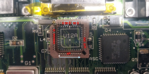
... I noticed that in the schematics the pins of the SWIM are labelled 35, 32, 36, 31 (as in the schematics of the Mac Classic) while mine are 29, 26, 30, 25 (6 less). I start counting anti clockvise from the rounded corner as per the picture
How is it possible? Can the SWIMS be so different one from another?
I checked several times the correct orientation, but it cannot be in any case because the 35, 32, 36, and 31 would end up in two sides of the ISWIM.
I dunno, I'm lost now ...
Is there a pinout of the SWIM? I did not find any


