• Updated 2023-07-12: Hello, Guest! Welcome back, and be sure to check out this follow-up post about our outage a week or so ago.

YABMP (Yet Another Broken Macintosh Portable)

Kalle

Member
Hi!
I have been looking through many threads regarding Macintosh Portable but unfortunately have not gotten any closer to a solution. Short story follows:

 Macintosh Portable M5120 (non backlit) with original power brick 1MB RAM. (white/light grey).
 Recapped about a year ago working fine back then.
 Built a battery using 6v/4,5Ah lead-acid sealed battery with 3D printed case.
 Bluescsi with Macintosh Plus .ini file in root of SD-card runnging Mac OS 6.0.8.
 Is REALLY cranky when booting from battery, one in 10 tries boots all the way to Finder, then usually crashes within a few seconds.
-SAD MAC codes are as follows
Most Common:
00000010
0000CD37

and

00000000
0000CD38

00000014
0000CD38

I also get:

00000011
00100000

03001300
00001FFA

0000000F
00000001

If I manage to get into Finder booting of batter power only sometimes the mouse keyboard or both stop repsonding after a few seconds

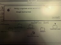
Booting with power brick and battery works much better, usually boots into finder, getting random crashes and wierd error messages.

Suspecting Hybrid IC/board but seem a bit random, RAM? Any other chip?

Regards, Karl


IMG_3350.jpeg
IMG_3377.jpeg
 

3lectr1cPPC

Well-known member
Not much to add but just letting you know that you linked the thread instead of the Hybrid board check.

Sure does sound like Hybrid to me though. Strange that it would pass fine, sounds like power is funky somewhere.
 

Kalle

Member
Not much to add but just letting you know that you linked the thread instead of the Hybrid board check.

Sure does sound like Hybrid to me though. Strange that it would pass fine, sounds like power is funky somewhere.
Yes sorry I mean to link:
https://androda.work/mac-portable-hybrid-pre-check/

I just noticed the linked spead sheet with a more extensive testing. Will give that a go. The hybrid chip with shipping and tax isn't that expensive compared to what I have spent on this machine in both time and money, might as well go all the way. :D
 

SuperSVGA

Well-known member
It definitely seems like there's either unstable +5V or some weird bus errors based on the errors.
If you have an oscilloscope you can look at the +5V to see if you see any fluctuation or drops.

If you're interested at all, here's what each error means:

Code:
00000010
0000CD37
0x10 is a failure when running the power manager self test. This test occurs after communication has some power on commands were sent to the power manager, so it didn't fail until now...
0xCD37 indicates a timeout while waiting for a reply to the initial handshake.

Code:
00000000
0000CD38
I'm not sure if this is a typo, because usually there's always major error code.

Code:
00000014
0000CD38
0x14 is a failure during power manager communication.
0xCD38 means the power manager never became "ready" and the system gave up on waiting.

Code:
00000011
00100000
0x11 is a failure while running memory sizing.
0x00100000 should refer to the first megabyte of expansion RAM.

Code:
03001300
00001FFA
This usually means the programmer's switch (next to the reset button) was pressed during startup. That line is active low and the button grounds it, so if the button isn't being pressed then either something is dragging the line down or the pull up resistor from +5V dropped too low.
0x1300 is a level 4 interrupt, and since the least significant byte is 0x00 no other errors occurred (yet).
0x0300 means bits 24 (unexpected exception) and 25 (NMI button) are set.
0x00001FFA is the current address of the stack pointer, not useful in this case.

Code:
0000000F
00000001
0xF means a system error like in your pictures occurred, but the error table was not loaded yet.
I believe 0x1 is "bus error".
 

Kalle

Member
@SuperSVGA
Thank you for your clarifications of the error codes. I'll whip out my oscilloscope and check the +5volt. Where is the best place to check? Q16 or somewhere on the hybrid board?

PS. I just ordered a repro hybrid board from you (?) on ebay yesterday. Even if the hybrid i not faulty it's alway good to have a spare board (the old one).

//Karl
 

Kalle

Member
Checked the voltages at Q16, they seem quite stable I am however a bit confused regarding leg 3 on Q16, i'm getting 6,2 volt on the source, i'm not an expert at reading schematics by any stretch of the imagination but I cannot see any reference to a 6,2 volt source.

Film of measurements
 

SuperSVGA

Well-known member
I'll whip out my oscilloscope and check the +5volt. Where is the best place to check? Q16 or somewhere on the hybrid board?
You can see the +5V from either the metal heatsink on Q16 or from pin 2. Occasionally the connection to the heatsink isn't great so if you have trouble getting a reading or it doesn't look right then check pin 2 instead.

Checked the voltages at Q16, they seem quite stable I am however a bit confused regarding leg 3 on Q16, i'm getting 6,2 volt on the source, i'm not an expert at reading schematics by any stretch of the imagination but I cannot see any reference to a 6,2 volt source.
6.2V is the voltage from the battery. Q16 brings it down to 5V.

Film of measurements
I'm guessing that oscilloscope isn't quite as accurate for voltage measurements but the voltage does seem a little low, usually you want to see around 5.1-5.2V just to account for any voltage drop further down the board. It's probably still fine at 4.9V but it also looks a little noisy on that scope as if it isn't stable, so if that's not just the scope then that could be a problem as well.
 

Kalle

Member
Thank you for your answers!
Yes, , that oscilloscope doesn't produce the cleanest signal, just a "toy osilloscope", I have a HP 16500B with all the bells and whistles but it's beast to move around. I'll wait until the new hybrid board arrives and I have it installed before I do any more fault searching
 

Kalle

Member
Finally I got the hybrid board and have it installed. Portable started to a question mark with no error codes but there was no +12 volt going to the BlueSCSI, after some fault searching I found out that the 12 volt was likely grounded to the metal holder for the hard drive at one point as the 34->50 pin adapter was "wobbly". So one step forward, and one step back.

Any ideas where to start searching for the missing +12 volt? Fuse? Voltage regulator?

//Karl
 

Kalle

Member
There only seem to be trouble with the SCSI power as far as I have been able to find out. This is all a bit of a mess, on the power pins in the SCSI connector I have +12 volt under no load, but as soon as load is apply a load the voltage seem to drop to almost 0v. The +5 volt is steadily going up from about 1,2 volt to 3,47 volt under a period of about a minute and stops at that voltage, as if a capacitor gets charged up. Q20 leg 1 gives me 5,41 volt, middle leg 3,42 volt and last leg battery voltage.
 

Kalle

Member
Ok, I could not let Q20 be alone, the voltages just did not add up in any kind of way. Under load the Gate voltage was 5,4 volt and the Drain was just 0,7 volt. I desoldered the mosfet and did a test that seemed "off" putting the mosfet in my chinesium IC tester kinda confirmed my suspicions it did not register a mosfet ( see image 1) just to be safe i desoldered Q16 (also a IRF 9Z30) and it registered as a mosfet on the IC tester. ( image 2). Time to find a IRF 9Z30 or equivalent! IMG_3497.jpg
IMG_3496.jpg
 

SuperSVGA

Well-known member
I've seen that happen before, I think I have one board that had Q20 requiring 10-11V on the gate to get up to 5V. It's a very unusual failure, I swapped the OpAmp with a slightly better one to give it an extra volt (the OpAmp+ is connected to +12V) since I didn't have a spare MOSFET.
 

Kalle

Member
The op-amp, would that be the OP-20 next to Q20? Any suggestion on a better one? Might as well swap it while i'm at it. I have ordered a few IRF 9Z34 which seem to be the direct equivalent to 9Z30. I wonder if I might have fried Q24 and/or Q25 as well, shouldn't I get 12 volt from them? I only get 5,4 volt to the source (pin one) on the Q20.
 

SuperSVGA

Well-known member
The op-amp, would that be the OP-20 next to Q20? Any suggestion on a better one?
I don't think there's any need to replace it, but if you need to replace one in the future the OP07CD series works fine.

The op-amp, would that be the OP-20 next to Q20? Any suggestion on a better one? Might as well swap it while i'm at it. I have ordered a few IRF 9Z34 which seem to be the direct equivalent to 9Z30. I wonder if I might have fried Q24 and/or Q25 as well, shouldn't I get 12 volt from them? I only get 5,4 volt to the source (pin one) on the Q20.
Q20 should have battery voltage on one side, and +5V on the other (when the +12V is on).
 

bigmessowires

Well-known member
Is it just the +12V supply that's not working? I don't think Blue SCSI actually uses the +12V supply. So while the absence of +12 is a concern, it's probably not the reason you can't boot from Blue SCSI.
 

Kalle

Member
Is it just the +12V supply that's not working? I don't think Blue SCSI actually uses the +12V supply. So while the absence of +12 is a concern, it's probably not the reason you can't boot from Blue SCSI.
The +5 volt is about 3,5 volt and the +12 volt seem to cut out as soon as there is a load. I have tried connecting the original hard drive and it also is dead. I'm waiting for spare parts (Q20 mosfet). Hope to get the parts by the end of the week and post an update here then.
 
Top