• Updated 2023-07-12: Hello, Guest! Welcome back, and be sure to check out this follow-up post about our outage a week or so ago.

Nearly torn cap on Mac SE/30, need advice

killvore

Member
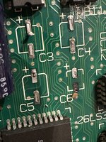
I was removing the bad caps from an SE/30 board and I think I've torn a pad! It's still hanging on for dear life, but I'd really appreciate some advice about how to proceed. I'm still very new to this, but I can get some help locally if it becomes necessary.
 

Attachments

  • IMG_8365.jpeg
    IMG_8365.jpeg
    1.4 MB · Views: 41

ymk

Well-known member
You could flow the pad and push it back down with tweezers. Install the cap and use a bit of extra solder to anchor it to the via.
 

68kPlus

Well-known member
You could flow the pad and push it back down with tweezers. Install the cap and use a bit of extra solder to anchor it to the via.
I second this. I lifted a few pads as my iron wasn't hot enough, and I did exactly this. Worked perfectly on my analog board.
 

killvore

Member
Phew, thanks for the tip and the reassurance! I am not sure what 'flowing the pad' means and I could not find a youtube video which shows how to do it. Is there some sort of procedure or is it simply "push it back down, then apply solder as normal and it will stick"?
 

NICfly

New member
I've had the same problem on my SE/30 with one solder pad on my recap and just soldered the replacement part very carefully on the loose pad.
 

mari3311

Member
If everyone's advice doesn't work, I wouldn't use a damaged pad.

Fix the capacitor that will be placed in the area where the pad came off to the PCB with a glue gun.
See schematic.

Connect the + terminal to the UB10 or UB11 terminal using the lead wire.
Use the lead wire to connect the - terminal to R12, R13 or GND.

If the pad is damaged with C8, C9, or C10, put a 0.3mmφ tin plated wire in the through hole at the tip of the capacitor pad and solder the tip of the tin plated wire to the capacitor terminal, but with C3-C6, This method cannot be used because the pad diameter is too small.
 

smrieck511

Well-known member
If everyone's advice doesn't work, I wouldn't use a damaged pad.

Fix the capacitor that will be placed in the area where the pad came off to the PCB with a glue gun.
See schematic.

Connect the + terminal to the UB10 or UB11 terminal using the lead wire.
Use the lead wire to connect the - terminal to R12, R13 or GND.

If the pad is damaged with C8, C9, or C10, put a 0.3mmφ tin plated wire in the through hole at the tip of the capacitor pad and solder the tip of the tin plated wire to the capacitor terminal, but with C3-C6, This method cannot be used because the pad diameter is too small.
should it just be gone, consider it a right of passage...It can be pretty straightforward to get it connected again to where it needs to be with a bodge wire or repair. Here's a great video that can help.


killvore

Member
This is really great, thanks a lot! I love this guys videos, it is very soothing to feel that it IS possible to fix these types of situations 😅
 

JC8080

Well-known member
This is really great, thanks a lot! I love this guys videos, it is very soothing to feel that it IS possible to fix these types of situations 😅
Everybody has done it, usually more than once. It's part of the hobby, and especially part of learning. There aren't very many ways to damage one of these boards that can't be fixed.
 

smrieck511

Well-known member
This is really great, thanks a lot! I love this guys videos, it is very soothing to feel that it IS possible to fix these types of situations 😅
yeah, solving problems and learning is 99% the fun of this hobby. It exercises the logical part of our mind...You need problems to solve problems.
 

nyef

Active member
My worst lifted-and-torn-pad repair, I ended up buying some two-part conductive epoxy (MG Chemicals 8331, not cheap), cutting pieces of copper tape the size of the pads that needed replacing, and using kapton tape to both help to position the replacement pads and hold them down while the epoxy cured. Also resecured the merely-lifted pads using conductive epoxy and kapton. After that, the lifted pads still had continuity, but the torn pads didn't (but were secure enough to hold the replacement capacitors), so at that point it was time to break out the magnet wire (I'm currently using 32 AWG, but will likely move to something finer at some point) to bridge connections.

I learned a lot doing that repair, including to use a board heater to bring the board temperature up before trying to desolder things, so that I have reduced "dwell time" with my iron (also run on the hot side, for the same reason) while removing parts (reduces stress on the adhesive holding the copper layer to the substrate).
 

irdc

Member
There’s also the twist method, where you gently twist the offending capacitor side-to-side until it’s pins break due to metal fatigue. The advantage of doing it this way is that the glue underneath the solder pads stays cool during the cap removal, which keeps it strong. Afterwards the remainder of the cap’s pins can be individually removed.

It’s admittedly a controversial method, though I’ve had good results with it on several boards now.
 

JC8080

Well-known member
There’s also the twist method, where you gently twist the offending capacitor side-to-side until it’s pins break due to metal fatigue. The advantage of doing it this way is that the glue underneath the solder pads stays cool during the cap removal, which keeps it strong. Afterwards the remainder of the cap’s pins can be individually removed.

It’s admittedly a controversial method, though I’ve had good results with it on several boards now.
I've never been able to bring myself to use the twist method, though many people swear by it, with few horror stories. If I'm not using hot air I generally use a pair of side cutters to cut the can off the base, as close to the base as I can get. I do this while applying downward pressure on the cap with my other hand. Once this is done you can remove the rest of the can and plastic base with tweezers, leaving just the two small legs, same as the twist method. Then you just remove the legs with an iron.
 

smrieck511

Well-known member
Of the four SE/30's I've recapped different ways, here was my experience...Ultimitely, you have to assess how strong the pads look in contrast to the cap legs.

Twist Method - Carefully applying a little downward pressure as well (never upward) - No damaged pads.

Hot Air - No damaged pads.

Soldering Iron, flux and wick - Lifted at least one pad.


Go slow and use some kind of magnification.
You may want to test out whichever method first on C1 which is out in the open on the board and relatively easy to repair compared to the other caps.
 
Last edited:

nyef

Active member
Dual irons is very safe and will not damage nearby plastics, as hot air can.
On this topic, kapton tape is heat resistant. Wide pieces can be used to protect plastics and components that you don't want to accidentally melt or desolder when you're using hot air. Or tape down something to use as an air (and heat) shield. Hot air alone can be fairly indiscriminate.
 

smrieck511

Well-known member
On this topic, kapton tape is heat resistant. Wide pieces can be used to protect plastics and components that you don't want to accidentally melt or desolder when you're using hot air. Or tape down something to use as an air (and heat) shield. Hot air alone can be fairly indiscriminate.
Yes, always use kapton tape on the surrounding area. Especially plastics.
 
Top