• Updated 2023-07-12: Hello, Guest! Welcome back, and be sure to check out this follow-up post about our outage a week or so ago.

My Maccon didn't survive the right angle operation...

BadGoldEagle

Well-known member
Yep, apparently my Maccon died. 

I can't see any damaged traces/chips (apart from the ones which were cut from the factory...) but perhaps I missed one?

Here's what I get on the display. (FYI, nothing else's plugged in, just the card without its daughterboard. SE/30 works otherwise well.)
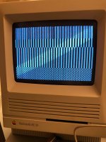
IMG_5449.jpeg

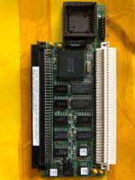
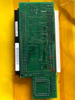
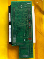
Here are some pictures of the board.
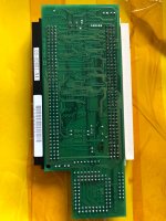
IMG_5452.jpegIMG_5451.jpeg

Any help appreciated :-/

Thanks


Bolle

Well-known member
If I remember right yours didn’t have a jumper wire installed on the back, right?

If it had one then that’s missing.

Check if you damaged the protective layer around the traces that run close to the passthrough solder spots.

It‘s possible that you are shorting one of them to one of your new solder joints.

The other possibility is that you ripped some pads/traces on the component side while removing the old connector. That didn’t happen to me yet though when removing those kind of connectors. If you pull too hard the contact usually just slides out of the plastic housing but it won’t rip out the pad on the board.

How did you remove the old connector anyways?

Worst case will be that you have to remove the new one again and check for damage on the component side once more.


BadGoldEagle

Well-known member
Hi Bolle

It has and always had two jumper wires near the original PDS connector. That didn't change. 

I checked individually every connection going from the old PDS to the new one. All of them work. I didn't do the greatest job ever, and apparently there's one line that connects all three rows. I don't know if that's normal or not. The legs aren't bridged together...

That leaves the pads on the other side (as you pointed out) or the chips themselves... 

I removed the connector by sucking every solder joint one at a time. The connector was a that point a bit loose so I jittered it a bit and it literally came apart. I was left with pins all over the board that I had to remove manually. I don't think it tore apart the pads but I guess that's a possibility. 

I tried my hot air gun but the solder just won't melt, even on the highest setting. I don't have a flux pen but I guess that would help. If I start over with the sucking method I might break that other connector and as you know, they tend to be quite costly. 


Bolle

Well-known member
Check if those are connected by accident:

IMG_5451.jpeg.bbe7ac38b1cb01f171cdbf3a7558bba8.jpeg

The solder blobs look quite big on the picture and if the protective layer over the trace that's running by is damaged right there you will short those two together.


BadGoldEagle

Well-known member
I went digging and found that these were connected. Doesn't look good.

IMG_5451.thumb.jpeg.fe794efcf096eb96169ade26f2f5a70b-2.png

And I can't desolder most of these joints. As if my iron isn't powerful enough... I remember having issues with those rows when I desoldered the old connector. Any idea what can be wrong on that front?


joethezombie

Well-known member
The cyan colored squares are all connected to the ground plane, so they should all be connected.  That's probably why it was harder to solder those ones, because there is a lot of copper there.

Now your red guys, the squared row on the bottom of your picture should all be connected, too-- they are all +5V (row 37).

The top red square, should also be connected to the other reds, as it is +5V as well (B19).

The next red square on A22 should NOT be connected to the others.  It is a data line.  So that is a definite problem if it is connected to +5V.  That trace runs along the right edge of the column in your picture, so check for a short at C37, perhaps the solder has flowed into the trace there.

Now your next red square on B24, it is also a data line and should not be connected to the other reds.  But I wonder if you just marked your picture wrong, as the next pin down at B25 should be connected to +5V.  But you don't have that pin highlighted.  Double-check that.

And finally the next red square at B31, it is also +5V, so no problem.

So, assuming you marked B24 instead of B25, the only real issue is the short on A22 to 5V.

Good luck!


BadGoldEagle

Well-known member
Thanks Joe!

You are right, it is B25, not B24. My bad, sorry! And the real 'issue' I'm having tonight is that A22 isn't connected to 5V anymore. That's good but why was I getting a reading earlier today? My multimeter beeps every 5 mins or so if you don't use it. It makes the same high pitched sound as if the two prongs were connected. That could be it...

Tomorrow I'll go hunting some more traces, but this time, I'll be armed with the pinouts!


I had completely forgotten that the upper PDS connector mirrors the one on the LB. Somehow I got into my head that there was some conversion involved. But even if that was the case, ground and power should still be at the same locations. 

 
Top