-
Updated 2023-07-12: Hello, Guest! Welcome back, and be sure to check out this follow-up post about our outage a week or so ago.
You are using an out of date browser. It may not display this or other websites correctly.
You should upgrade or use an alternative browser.
You should upgrade or use an alternative browser.
Macintosh Portable 34 pin to 50 pin SCSI cable
- Thread starter martona
- Start date
Trash80toHP_Mini
NIGHT STALKER
Nope, IIRC it has a video out port to which very little has ever been attached or used for anything all that useful.
http://support.apple.com/kb/TA45501?viewlocale=en_US :-/
Nice adapter, uni! 1/2" or 3/4" Plexi? I was looking at doing a simplified sheet metal bracket, the one in the Luggable is just stupid!
http://support.apple.com/kb/TA45501?viewlocale=en_US :-/
Nice adapter, uni! 1/2" or 3/4" Plexi? I was looking at doing a simplified sheet metal bracket, the one in the Luggable is just stupid!
uniserver
Well-known member
looks like hap is starting to sell them.
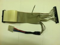
A 34pin to 50pin SCSI adaptor/cable /w molex connector
http://www.ebay.com/itm/Macintosh-Portable-M5120-M5126-Custom-34-to-50-pin-Adaptor-Cable-SCSI-HD-/151059342613?pt=US_Drive_Cables_dapters&hash=item232bd6a515
A 34pin to 50pin SCSI adaptor/cable /w molex connector
http://www.ebay.com/itm/Macintosh-Portable-M5120-M5126-Custom-34-to-50-pin-Adaptor-Cable-SCSI-HD-/151059342613?pt=US_Drive_Cables_dapters&hash=item232bd6a515
Trash80toHP_Mini
NIGHT STALKER
PCB time.
Trash80toHP_Mini
NIGHT STALKER
This is as good a project as I can think of for me to learn to do files for Seeeding some boards. :approve:
What's the best demo PCB design tool for small boards or least expensive small board license for a commercial tool for Mac or PC/Win7/Ubuntu? Mac preferably, but I've always gone to the platform with the correct tool for the job instead of the other way around.
What's the best demo PCB design tool for small boards or least expensive small board license for a commercial tool for Mac or PC/Win7/Ubuntu? Mac preferably, but I've always gone to the platform with the correct tool for the job instead of the other way around.
Check out Osmond PCB. I've been using it since it was beta back in 2000 or thereabouts. All of my printed circuit designs, ANS CPU adapter, Beige G3 ROM, IIfx RAM, have been done with Osmond and the Gerber files output from there.
http://www.osmondpcb.com/index.html
The free download will let you do any design and layout that the paid version will, but you won't be able to output your design to Gerber or Postscript files if it has more than 700 pins. Pins are inflection points (and ends?) to traces.
So small designs can be done for free and output for fabrication. Large designs can be made for free, but one must buy the software in order to output a file for fabrication.
Scroll down on the "Download" page for legacy versions, including a System 8.1 PPC version.
Do the tutorial.
You can create and edit parts in Osmond, for example the 64 pin SIMM connector for the IIfx RAM, and the Mac II ROM modules. Designing is much easier if you first create the parts. Then layout the parts in your design, create a rats nest of connections, and then route the rats nest into a usable board.
I did not find the auto-routing to be very good, but I have not tried it again since 2001. It may have improved.
Trash80toHP_Mini
NIGHT STALKER
I was looking at my Luggable and the Conner HDD's board to cable connection looks kinda funky. Is it a hardwired/soldered inter-board cable connector setup or a RA male-female header pin type deal?
Trash80toHP_Mini
NIGHT STALKER
I'm looking into butchering (key-slotting one side) of a 40/80 PATA cable to plug into the Luggable's 34pin header connector. It's a question of length, whether or not all the lines are implemented a/o the MoBo connector is plugged or set up for VCC on pin 20.
Looks promising. Rounded ones are available! [ ] ]'>
] ]'>
Looks promising. Rounded ones are available! [
Trash80toHP_Mini
NIGHT STALKER
Trash80toHP_Mini
NIGHT STALKER
I'm thinking a short, round, single device cable with VCC on pin 20 instead of a plug. I'll be looking into the slave/master section of dual cables, but that's looking iffy. Half the key needs to be cut away in any configuration. Cutting it off entirely and reversing the connector may be necessary for the dual device end, but it looks like you can't plug it in backwards after the connector is notched any which way. The battery plug and edge of the chassis act as a keying mechanism. [ ] ]'>
] ]'>
Trash80toHP_Mini
NIGHT STALKER
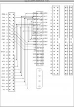
. . . way too ugly!  Besides, I think my PCB layout got badly borked when I flipped a component around. About the time I relaxed about the cabling problem and girded for a re-do of the PCB connections, it hit me. I HATE soldering, so the notion of building TWO custom cables using standard IDC methodology and reducing the connector count on the PCB to zero finally dawned on me as the most simple of possible adaptations! [
 ] ]'>
] ]'>
Has anyone with a Luggable got an old school floppy cable for the PC handy, the kind that still has edgecard connectors alongside the header interfaces?
Card edge connectors fit fine in the space underneath the HDD, but will the connector with ribbon cable folded over fit under there? It doesn't need to slide under, it only needs to be possible to set it in place and install the HDD above it. The adapter PCB will be parallel to the HDD, the 34 and 50 pin edgecard connector cables on either side of the adapter PCB act as standoffs and strain relief.
If someone could check the fit for me I'd appreciate it, It'll take me a week to figure where I've hidden my old PC cables.
If this approach works out, the only soldering necessary will be the four leads from the MOLEX Connector to the adapter PCB. [} ] ]'>
] ]'>
Has anyone with a Luggable got an old school floppy cable for the PC handy, the kind that still has edgecard connectors alongside the header interfaces?
Card edge connectors fit fine in the space underneath the HDD, but will the connector with ribbon cable folded over fit under there? It doesn't need to slide under, it only needs to be possible to set it in place and install the HDD above it. The adapter PCB will be parallel to the HDD, the 34 and 50 pin edgecard connector cables on either side of the adapter PCB act as standoffs and strain relief.
If someone could check the fit for me I'd appreciate it, It'll take me a week to figure where I've hidden my old PC cables.
If this approach works out, the only soldering necessary will be the four leads from the MOLEX Connector to the adapter PCB. [}
uniserver
Well-known member
yes those have to be grounded or the cable will not work.
i think it would be better to attach them to the corresponding spot on the IDC,
be careful with the 50pin side, once you get it working i would epoxy the wires to the IDC because they are quite fragile when you put the wires in the idc like that. even if you have the additional strain relief, you still should put some epoxy or something for a greater mechanical/electrical connection, reliability. Or else you will have a monkey fingers day and rip the wires right out of the 50pin IDC.
Last edited by a moderator:
Similar threads
- Replies
- 7
- Views
- 517
- Replies
- 7
- Views
- 506
- Replies
- 3
- Views
- 751
- Replies
- 2
- Views
- 339
- Replies
- 29
- Views
- 2K

