• Updated 2023-07-12: Hello, Guest! Welcome back, and be sure to check out this follow-up post about our outage a week or so ago.

macintosh classic questions..

chelseayr

Well-known member
I assume that the ram upgrade, if any were present, is simply pulled upward to get out right? and if any hdd was already there did that have to be removed first or not so much?

and does the logic board really just simply slide out of the rear 'tool less ly', a little alike to how it does so on the performa models?

just curious roughly how deep the two top t-15 screws are in?
not sure if I may have to find something else (may be able to borrow it from a particular torxs-happy workshop but will see soon)

is the checkers-like crt capacitor pattern one of these 'either it has it or it does not have it' or do some systems actually show it for a while but then it seem to be normal afterward tho? just wanted to know what to expect (the ad photo showed the question mark icon without any visible screen issue but it may or may not be as well as a different story for me soon)
 

Nixontheknight

Well-known member
I assume that the ram upgrade, if any were present, is simply pulled upward to get out right? and if any hdd was already there did that have to be removed first or not so much?

and does the logic board really just simply slide out of the rear 'tool less ly', a little alike to how it does so on the performa models?

just curious roughly how deep the two top t-15 screws are in?
not sure if I may have to find something else (may be able to borrow it from a particular torxs-happy workshop but will see soon)

is the checkers-like crt capacitor pattern one of these 'either it has it or it does not have it' or do some systems actually show it for a while but then it seem to be normal afterward tho? just wanted to know what to expect (the ad photo showed the question mark icon without any visible screen issue but it may or may not be as well as a different story for me soon)
the top t15 screws are inside the handle, so it's best to use a really long Torx screwdriver to get them out. Hard drives and floppy drives had to have their cables removed, along with the cable to the analog board, before removal. The logic board rally does slide out toollessly, like the Performas, except you have to remove cables. You just have to pull the ram upgrade up to take it out, and it must be removed before pulling the logic board out. For the checkerboard pattern, it usually indicates the analog board cannot provide enough voltage to the logic board to start it up, if the Macintosh Classic you are looking at does not have it, it does not mean it will not for a long time, you have to have the logic board and analog board recapped as soon as possible. If you are not comfortable recapping it yourself, there are people in this forum that will be more than happy to do it for you themselves
 

chelseayr

Well-known member
thanks will check about a long t-15 with someone else then as I only have the usual short length ones available to take,
as for recapping yeah i'll indeed have to look at the present post-disassemble condition and see where to go from there

cheers
 

crazyfrog

Active member
I’ve just come back to one of these after doing all the fixes the internet says to do and not getting anywhere but catastrophic failure with blown fuses and diodes. Tonight I found a failed 1n148 diode on the neck board shorted to Earth. Since dp3 and dp4 are known for failing on these I’m thinking the original they’re prone to failure.

I’m looking forward to getting things powered on again and seeing how far into the board I get voltage as last time it was only on the primary side after replacing the mosfet and diodes there.
 

chelseayr

Well-known member
@Nixontheknight looks like I'll have to get a t15 off a stranger somewhere else..assuming it didn't use a very fat handle on the top (as some very short screwdrivers commonly do) I should be ok with anything that has at least 4" of shank on it?
 

Nixontheknight

Well-known member
@Nixontheknight looks like I'll have to get a t15 off a stranger somewhere else..assuming it didn't use a very fat handle on the top (as some very short screwdrivers commonly do) I should be ok with anything that has at least 4" of shank on it?
it should be a pretty long t15 screwdriver, so you could try looking on amazon
 

crazyfrog

Active member
Not on this CRT but its more of issue getting a long trim pot adjustment driver when you're working on larger crt monitors and displays.
 

chiptripper

Well-known member
@chelseayr I have a screwdriver kit with an extender that works like a charm for the T15 screws in the handle. “Mastercraft 66-piece precision screwdriver kit” from Canadian Tire, lots of bits, has been very useful.

FYI I find Classic and Classic II cases are both very hard to pull apart even after the screws come out… tight fit near the top and it gets kind of stuck. They DO come apart, just have to kinda wiggle on one side, then the other.
 

chiptripper

Well-known member
Yes that's the one I have. I just use the solid extender shank, which adds about 4 or 5 inches to it. A basic T15 screwdriver would cost less (I see one with a 4" shaft for $10 on Amazon) but I've more than gotten my money out of this kit. I actually have two, one from Can. Tire and one generic, both work for cracking compacts.
 

chelseayr

Well-known member
well it took a while to finally actually take the T15 bit out of the mastercraft bin but hm apparently the previous owner had simply omitted putting the two deep torx's back (I was wondering why nothing was biting at all till I asked relative if there was a little flashlight around and mm sure enough nothing in these two deep-recessed holes there!) leaving only the two somewhat-tightly-hard-on lower torx's alone to deal with

but anyhow after trying to figure it out for a short awhile the front just simply rumbled forward rather easily

it seem like this particular macintosh classic had already been separated quite a few times as the edge are rather worn (including deep paint scrap off the internal skin) but interestingly enough the specific area of dust and bit more suggests that otherwise little actual work was done inside other than for to pull the main logic board out at least once or more as the difference in surface dusts would suggest

interestingly enough I was just about able to spot it without doing any further work but it looks like the current battery in there is the kind thats white for the cylinder and green for the edge trims (but I suspect colour doesn't really exactly identify a battery age tho right?) .. and no apparent leak signs either in front of it or on the pcb underside

and mm one final thing..
it apparently does have a hdd but I'm not sure whether it simply has no system folder on there or is mechanically dead, I'll have to get around to sorting a bootdisk as per another topic I made before .. and to see if the disk drive works for me to get to a desktop stage as to then see what I can figure of the internal hdd it has

either way as the hdd was mounted upsidedown (no surprise if that was suppose to be normal for these systems?) I can't read a direct tag off it atm but I did note these two chips 'on the back' tho;
conner
61106-001
GC27E
+
adaptec
AIC-610L
ZGC106

is that too vague or do we apparently know what capacity range this might had narrow it down to?

I naturally don't feel like trying to play around with that vertical power board hence I can't reach the one other screw needed to get that hdd out (and maybe even the disk drive too? or did that one not depend on a "blind side" screw too otherwise?)

at least tomorrow i for sure can hopefully want to get around to getting the power header unplugged as to pull the logic board to double-check on the battery itself

sorry for such a long update to this thread ;-)
 

chiptripper

Well-known member
I've seen those green and white batteries before, circa mid-90s? Unless it's a modern Saft, which will have the date printed.

Easiest way to get the drive out is to just pull the whole caddy, FDD and all. Disconnect all cables, then there are four screws that hold the caddy in place, two on the sides, two on the back, they all should be accessible. Once you have the screws out, lift the back (to free two metal tabs that slot into the front) and pull the assembly out. Just mind you don't bump the neck board while pulling the drive or yanking stubborn cables.

HDD is probably a 40mb Quantum Prodrive LPS. It might be stuck, or the Classic might have low voltages that prevent it from spinning up. Guessing the former but it's very worth checking voltages anyway.
 

chelseayr

Well-known member
hmm I did wonder if the drives actually meant to come out without having to pull the power board itself too, thanks. will try have a look at that whenever I can get around to it later in the week

on a side note I wonder whats with the previous owner(s) rapidly splashing pink paint onto much of these evenly spaced nubs populating the large ring of the crt assembly itself

anyhow I may be able to also get photos too at the same time I work on this again the next time.. :)
 

zigzagjoe

Well-known member
Those nubs are magnets to control the geometry of the picture on the CRT. Rotate them, and it stretches/compresses either the corners or the edges of the image. The paint is to prevent them from being moved without deliberate force. They are factory set and rarely benefit from being changed.
 

chelseayr

Well-known member
ah ok, I wondered if the pink paint was something from factory or 'what were you thinking?' not. thanks for that
 

chelseayr

Well-known member
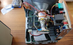
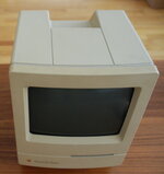
well the sun was already a little weak not long before supper (as far as the current temp workspace's location went) but I still managed to get these three good photos for now

naturally after the last photo I then managed to unplug the board out (and left it dangling unplugged back into the case afterward just to make it a bit easier a next free day) and anyhow about that - the battery was a saft lsl3 from france, and it had 'F.91.164A' stamped onto it. I guess i'll dispose of it next time I stop by a library most likely?

oh and don't mind the extra gap around case frame in first photo, I just was lazy at not trying to 100% put it back together when I knew I was going slide it out again later in the week etc

i'm still a little curious about the seemingly random applications of glue glop at many places not to mention a bit of it right at (on very top) where the tube attaches to the plastic holder that then is soldered to the pcb. but either way seeing that the two original high-voltage papers are still there intact I hopefully can correctly guess that nothing had ever been replaced yet pcb-wise, at least from what I can see the power capacitors still look very straight and flat for now

DSC_0871.JPG
DSC_0873.JPG
DSC_0876.JPG
[p.s @chiptripper do you spot something familiar? heh!]
 

chiptripper

Well-known member
Haha yes I do! Guess I'm a Mastercraft brand rep now...

From what I can see your Classic looks in good shape internally, everything looks as expected. The glue globs are normal, factory additions to keep components from getting dislodged, I guess? If you need to remove the glue (during a re-cap, say, or to detach the neck board) just dab a little isopropyl alcohol on the glue glob, it de-stickies it like a charm.
 
Top