• Updated 2023-07-12: Hello, Guest! Welcome back, and be sure to check out this follow-up post about our outage a week or so ago.

LocalTalk... but faster?

Mk.558

Well-known member
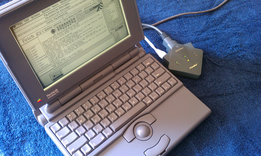
It does work with FTP, WWW, whatever you like TCP/IP protocol without the MacIP bridge. This PowerBook 170 was connected directly to the Internet via the Ethernet cable out of the EtherWave.

47di10mq.png


I think that our best option would be the TashTalk with some kind of clock input control with a macipgw server for routing TCP traffic. I'm curious about one thing: If the Farallon device clocks HSKi at 1.25MHz, why not just replicate that? A hardware switch that turns on HSKi at 1.25MHz if the switch is on means you can keep compatibility with 230.4kHz if you need to. I don't know what we'd need a software driver on the client Mac side for because the clock rate is a hardware level thing.
 

dougg3

Well-known member
Unfortunately a lot of my research about the EtherWave Printer Adapter has disappeared into the ether, but I thought I would share a couple of snippets from my old forum post about how I believe it works. I reserve the right to be incorrect about anything I say below since it was almost 10 years ago, haha.

The LocalTalk Side:

When the EtherWave boots up, it obtains a server node ID on the LocalTalk network it's hooked up to (it gets 0x81 in my case). It also makes sure it doesn't have a name conflict with anything else on the network. It pretends to be a router by periodically sending out a small routing table in an RTMP packet. This routing table is only used by the LocalTalk computer that the EtherWave is hooked up to. It serves two purposes: 1) it tells the computer that its tiny LocalTalk network's ID is 0xFEFF. 2) It tells the computer that networks 0xFF00-0xFFFE can be accessed through the EtherWave (node 0x81).

Without the EtherWave posing as a router, I don't think the computer hooked up to it on the LocalTalk port would have any idea how to respond to a received packet that came from networks 0xFF00-0xFFFE, which are the network IDs that are automatically used by EtherTalk devices.

The Ethernet Side:

I was starting to expect that we'd see a similar thing on the Ethernet side, but nope. There are no RTMP packets on the Ethernet side, confirming that the EtherWave is not a router. On the Ethernet side, the EtherWave grabs a node address on network 0xFF00, just as if it were another EtherTalk computer. It appears to me that it uses this EtherTalk node address to spoof anything on the LocalTalk side so that it appears as if it was coming from this EtherTalk address.

So for example, my LocalTalk IIci's address is network 0xFEFF, node 1. My EtherWave's address is network 0xFF00, node 93. As far as I can tell, all other EtherTalk devices think that my IIci is an EtherTalk device with the address "network 0xFF00, node 93". It has no idea that it is actually a LocalTalk device. The EtherWave spoofs the addresses when communication goes in and out of the LocalTalk side. Nothing on the Ethernet network is even aware that the network 0xFEFF exists. Each EtherWave Printer Adapter makes a little mini 0xFEFF network that is only visible to itself and the computer/printer it's connected to.
 

uyjulian

Well-known member
I wonder if it would be possible to use both the modem and the printer serial ports together for faster speeds.
 

joevt

Well-known member
The SCC has a few clocking options:
  • DPLL from RXD : I'm not sure how this is useful - how can you receive data if RXD is used for the digital phase locked loop?
  • TRxC from HSKi: The normal external clocking method.
  • RTxC from 3.672 MHz: used for 115.2 kbps or 230.4 kbps using X16 or X32 asynchronous clock mode. Also can do 57.6 with X64 asynchronous clock mode.
  • RTxC from GPi: Alternative external clocking method. Test for this using gestaltHasGPIaToRTxCa for modem port. It's not available for printer port. Change the source of RTxC using _HWPriv as described in "Technote DV 16 - Serial GPi (General-Purpose Input)". Usually GPi is connected to DCD for both ports. Check gestaltHasGPIaToDCDa and gestaltHasGPIbToDCDb.
  • Baud Rate Generator from 3.672 MHz: This is used for normal baud rate modes up to 57.6 kbps using X16 asynchronous clock mode. The minimum Baud Rate Generator constant is 0 which effectively divides the clock by 4 (3.672 MHz / 16 / 4 = 57.6 kbps). A BRG constant of 1 divides the clock by 6. A BRG constant of 2 divides the clock by 8. And so on.
  • Baud Rate Generator from GPI.
  • Baud Rate Generator from PCLK. The PCLK is ≈13.2MHz on my Power Mac 8600. In that case, the effective max (13.2MHz ÷ 4 = 3.3 MHz) is not better than the 3.672 MHz taken directly from the RTxC pin. However, my B&W G3 has a PCLK of ≈22 MHz which would yield a clock of ≈5.5 MHz and a baud of ≈344 kbps.
The only way to get faster than 230.4 kbps is to use an external clock or to switch to synchronous X1 clock mode.

Synchronous X1 clock mode can only be used if both the receiver and transmitter are using the same clock which means one of them needs to take the clock of the other (external clock).

Maybe you can use two serial ports. One for outputting a clock and the other for receive / transmit. You can output synchronous bits as a clock that can be used asynchronously by the other port.

The SCC has a TRxC Out option which maybe outputs a clock from XTAL (PCLK or 3.2768?), Transmit clock, BR generator output, or DPLL output. Since TRxC is connected to HSKi, maybe it can be used as a clock source? I haven't tested that.

Of course the simplest option is to just have an external clock instead of trying to make the 3.672 MHz or PCLK external. However, the latter might be interesting if you want to try getting faster speeds between two Macs with just a serial cable and no extra hardware.

ADB Analyzer 3.png
 

cheesestraws

Well-known member
Each EtherWave Printer Adapter makes a little mini 0xFEFF network that is only visible to itself and the computer/printer it's connected to

This leaves me with a couple of questions, which you may or may not know!

  1. Does this mean the EtherWave will not play nice on networks that have routers on, or does it pass those through with RTMP?
  2. How does this deal with EtherTalk nodes in other parts of the startup network range?
 

tashtari

PIC Whisperer
TRxC from HSKi: The normal external clocking method.
Thanks for all the information - I didn't know ADB Analyzer also had an interface for messing about with serial port settings. Assuming they don't get reset at some point, that could be a good way to play around with external clocking. Is there any compelling reason to use anything besides HSKi, though? It's available on both ports, and according to the SCC's manual, you can use it for both the receive and transmit clock.

My current area of interest is in sort of cheating with the external clock, using it to clock in/out bits when the external system is ready to transmit/receive them rather than recovering the clock from the composite signal. I'm wondering if it's as straightforward as it could be - that is, that in SDLC mode, there's always an inversion on TxD on the rising edge of the clock, and there's also an inversion on TxD on the falling edge of the clock if the SCC wants to transmit a zero...
 

tashtari

PIC Whisperer
Thing is, I don't really see the reason to replicate this mess when we have new SCSI-to-Ethernet adapters.
There's also the potential use case of pre-SCSI Macs. I like the idea of a board that plugs into one of the DE-9 serial ports and goes straight to Ethernet (helped along by the +5V output on the DE-9).

But, for me, this is more of a because-it-was-there thing, not necessarily a practical thing. =)
 

Phipli

Well-known member
There's also the potential use case of pre-SCSI Macs. I like the idea of a board that plugs into one of the DE-9 serial ports and goes straight to Ethernet (helped along by the +5V output on the DE-9).

But, for me, this is more of a because-it-was-there thing, not necessarily a practical thing. =)
There is also the Unix / Linux principle of "do one thing well".
 

dougg3

Well-known member
I also took some high-res scans of my EtherWave Printer Adapter's PCB many moons ago.

Does this mean the EtherWave will not play nice on networks that have routers on, or does it pass those through with RTMP?

That's a great question. Unfortunately my only tests were on a network that didn't have a router so I don't know for sure.

The setup utility lets you pick which zone you're on, so I'm assuming there are some smarts in there for something. Getting this utility working with a MAC address ending with 00:00 was...interesting. It would complain that the adapter is not serialized and to contact Farallon for help, but I cheated and patched out the serialization check in the setup utility. (BTW, it's kind of funny that printer compatibility mode was off by default on my EtherWave Printer Adapter... :))

AdapterSetup.png

My assumption is that what I described earlier about the EtherWave sending out an RTMP fake router packet on the LocalTalk side containing 0xFF00-0xFFFE is really generalized to "whatever networks actually exist on the EtherTalk side" and in my case it just used the startup range since there wasn't a router.

It does bring up an interesting question of "what if network 0xFEFF actually exists on the EtherTalk side?" though. Maybe it would pick a different fake network number to use on the LocalTalk side in that case.

How does this deal with EtherTalk nodes in other parts of the startup network range?

I'm probably misunderstanding your question -- but isn't 0xFF00 through 0xFFFE the entire startup network range? As long as the EtherWave's EtherTalk side obtains an address in that range, all it really has to do is listen on that network/node combination and translate packets destined to it into LocalTalk packets destined to the Mac/printer on the LocalTalk side.

There would definitely be some translation of the packet contents needed though, if any protocols actually contained the node ID in the packet contents...that's the crummy part about this scheme of being a fake router instead of a real router.
 

cheesestraws

Well-known member
I'm probably misunderstanding your question -- but isn't 0xFF00 through 0xFFFE the entire startup network range? As long as the EtherWave's EtherTalk side obtains an address in that range, all it really has to do is listen on that network/node combination and translate packets destined to it into LocalTalk packets destined to the Mac/printer on the LocalTalk side.

Oh, so it's essentially doing bidirectional NAT, and the address of the computer attached via LT disappears entirely? Got it.
 

dougg3

Well-known member
Oh, so it's essentially doing bidirectional NAT, and the address of the computer attached via LT disappears entirely? Got it.

I didn't think of it that way until you said it, but that's exactly what's going on. I suspect this scheme doesn't support having multiple computers/printers on the LocalTalk side either. Which kind of makes sense based on how they designed it to plug directly into the serial port of a computer/printer.
 

DBJ314

Member
Maybe you can use two serial ports. One for outputting a clock and the other for receive / transmit. You can output synchronous bits as a clock that can be used asynchronously by the other port.

If you are going to use two serial ports, you might as well use both of them for data and get double the speed. And then use the HSKo and GPi pins (HSKi would be used for the external clock) to bit-bang an extra bit of data per time period, to slightly increase the data rate even more. Crank the external clock up as high as it will go, and that's probably the maximum bandwith possible from the SCC.
 

Phipli

Well-known member
Given the computers only have one thread and one serial controller, wouldn't using two ports just cause contention and not result in any speed increase, possibly a speed reduction? Until you hit the speed limit of the serial chip, surely you might as well just clock one port faster?
 

NJRoadfan

Well-known member
I didn't think of it that way until you said it, but that's exactly what's going on. I suspect this scheme doesn't support having multiple computers/printers on the LocalTalk side either. Which kind of makes sense based on how they designed it to plug directly into the serial port of a computer/printer.
Just seems weird to do it this way, unless someone wanted to reuse code paths in firmware (since the device supports network bridging). That or its needed for whatever transparent MacIP TCP/IP bridging the driver and firmware in the device itself is doing.

You can put a lone LocalTalk client transparently on an EtherTalk network. Just do short-long DDP packet translation and give the LocalTalk client an address by triggering AARP calls whenever the Mac sends lapENQ packets looking for an address.

Also of note. Farallon's bridging code for their normal Localtalk-to-Ethernet gateways does have some bugs in it. I know the Apple II AppleTalk stack needs some patching, otherwise it will lockup/crash the machine!
 
Last edited:

joevt

Well-known member
Thanks for all the information - I didn't know ADB Analyzer also had an interface for messing about with serial port settings.
It doesn't. I reverse engineered it to see how it works, then added the rest after reading the SCC data sheets and Apple tech notes.

Is there any compelling reason to use anything besides HSKi, though? It's available on both ports, and according to the SCC's manual, you can use it for both the receive and transmit clock.
I'm not sure. If you use anything other than HSKi for the clock, then HSKi could be used as an output of a clock using the TRxC Out option?
I made a note "- Test if CTS is connected to TRxC on LC or G3. They are not connected on B&W G3 or Beige G3 233" but that was 23 years ago so I don't remember what a G3 is compared to a B&W G3 or Beige G3 233. Maybe I meant 8600 with G3 upgrade? Probably not.

There's also a note "- Add crystal oscillator option to RTxC (D7 of WR11)." So maybe that's another clocking option that I missed? The SCC has so many options that I did not try them all.

The document I used was "Am8530H/Am85C30 Serial Communications Controller 1992 Technical Manual". It seems more descriptive than a Zilog document I found.

The AMD document says D7 of WR11 has some other purpose for SDLC mode. Section 5.2.1 "Crystal Oscillator" has more info about the non-SDLC mode function of that bit. Also section 6.2.12 "Write Register 11 (Clock Mode Control)". When searching for the function of a bit, you need to look for the register in this form "WR##" and this form "Write Register ##".

I have a note "WR6 is sent during transmit underrun.". This means you can put a pattern in WR6 and it will be transmitted in a loop without having to do extra work? That's for monosync mode. You can use the combination of WR7 and WR6 in bisync mode. I used this 2 byte pattern to test receive/transmit of a single byte in my Playstation to serial port adapter (it had no microcontroller just logic and flip flops). If TRxC can't be used as an output, then as an alternative, one could transmit a clock on TxD of a port by using a monsync pattern like 0xAA or 0x55.

Here are some other old notes that I don't remember all the details about. I had a CRT oscilloscope or digital multimeter when making these measurements.
Code:
HSKo: 1=4.03V 0=-4.27V
TXD+: RTS 1 (1=high=4.04V 0=low-4.27V) RTS 0 (TXD 1/0 = 0V)	(0V is on the positive side)
TXD-: RTS 1 (0=high=4.04V 1=low-4.27V) RTS 0 (TXD 1/0 = 0V)

HSKo to RXD+: no invert
HSKo to RXD-: invert
HSKo to GPi:  no invert
HSKo to HSKi: invert

TXD+ to RXD+: no invert
TXD+ to RXD-: invert
TXD+ to GPi:  no invert
TXD+ to HSKi: invert

HSKo to RXD+ = 2 bit delay
HSKo to GPi or HSKi = instantaneous (next read of RR0)
TXD+ to RXD+ = 12 bits
TXD+ to GPi or HSKi = 10 bit delay
	8 bit shift + 8 bit buffer + 2 bit delay
	when no bits exist in 8 bit buffer, then they appear tx buffer empty.

GPi floats at -1.2V gives bit value=1
GPi to ground gives bit value undefined.
GPi to +5 gives bit value 0.

inverter input floats at 1.6V			output floats at:.05V
inverter input ground gives output 4.07V
 

tashtari

PIC Whisperer
I reverse engineered it to see how it works, then added the rest after reading the SCC data sheets and Apple tech notes.
Oh, neat, you have a modded version with those options, then? Would you be willing to share it?

I'm not worried about having the Mac generate the clock itself, in fact what I'm planning depends on having the PIC do it so it can suspend clocking when it's doing other things like servicing its UART. Exactly how I'm going to make this work I don't know yet, but that's why I'm looking to experiment. What I'm hoping is that the SCC in SDLC mode takes the external clock and uses both of its edges - that is, a rising edge always causes the output to invert and a falling edge causes the output to invert if a zero is to be sent (or vice versa)...
 

joevt

Well-known member
Oh, neat, you have a modded version with those options, then? Would you be willing to share it?
The code is based on ADB Analyzer 1.0d6. I think that came with a control panel named DigiCal? I don't remember using DigiCal. I think you can download these from Apple or somewhere.

ADB Analyzer 2 is my reverse engineered version of that. I used Jasik's Nosy to do the disassembly. Each procedure is saved as a text file and the disassembly is manually translated to Pascal stored as comments in those files. Then I use an MPW script to extract those comments into a Pascal source file.

ADB Analyzer 3 was created with that as the base, and adds new features, resizable windows, and preferences. I don't remember if the ADB Analyzer 2 functionality still works. There's three versions but I don't remember what all the differences are:
  • "ADBAnalyzer3repro" - I think I lost some source code at some point so I had to reproduce some of it? I don't know if I recovered everything. I wasn't into source control back then except for MPW's projector.
  • "ADBAnalyzer 3" - the main version, I think?
  • "ADBAnalyzer 3 on the 8600" - The main version was hanging when running on my 8600 this week. Previously I was using a B&W G3 during most of the development. I fixed the hang by removing some code that waited for underrun to be set in the timing code. There's probably a more correct fix.
I think CodeWarrior Pro 4 (IDE 3.3) is best for compiling this since it includes Pascal 68K.
CWPro6 (IDE 4.1.0.3) has Pascal only for PPC? The Pascal files are best viewed with Geneva 9 point, tab spacing: 4.

InitializeSCCPort is used to program the SCC. It performs a series of register writes in the required order as described by the SCC data sheets. The registers and values are listed in InitTables. There's an InitTable for each function.
  • gClockTimerInitTable for determining the serial clock frequencies. This is modified for each clock source.
  • gResetTable for hardware reset after testing the serial clocks.
  • gADBAnalyzerInitTable for the ADB Analyzer functionality.
  • gSerialAnalyzerInitTable for the Serial Analyzer functionality. I think this still needs some work? I haven't tried most of this in a couple decades. The Serial Trace is like the ADB Trace part of the ADB Analyzer except that it does both serial ports simultaneously and includes all the status bits from the SSC.
  • gLoopModeInitTable for doing loop mode in the Serial Analyzer functionality.

I'm not worried about having the Mac generate the clock itself, in fact what I'm planning depends on having the PIC do it so it can suspend clocking when it's doing other things like servicing its UART. Exactly how I'm going to make this work I don't know yet, but that's why I'm looking to experiment. What I'm hoping is that the SCC in SDLC mode takes the external clock and uses both of its edges - that is, a rising edge always causes the output to invert and a falling edge causes the output to invert if a zero is to be sent (or vice versa)...
The SCC has different data encoding options : NRZ, NRZI, FM0, FM1. There's also a Manchester decoding option. I'm not sure what mode you need to use.

With my Playstation to Serial port adapter, I used a 555 timer for the clock with a potentiometer to adjust the frequency. It could read / write to Playstation controllers and memory cards at ≈ 1Mbps (also multiple controllers and memory cards using the Playstation Multitap). A lot of the logic had to due with pausing and starting the clock being sent to the Mac serial port - part of the transformation of the asynchronous serial output from the Mac to the format/timing required by the Playstation device. It transmits a byte back to the Mac for every byte that the Mac transmits to the Playstation device. "Asynchronous" in this context means that the Mac is including or expecting a start bit, a zero which is not transmitted to the Playstation device, and a stop bit which only serves as a gap between bytes (the stop bit is a one which just looks like serial idle). I used LogicSim 3.0b to create and simulate the circuit. I think at one point I was using the ADB port of a keyboard connected to a Mac LC to power the adapter bread board but that might not have been a good idea...
 

Attachments

  • ADB Analyzer 1.0d6.zip
    21.6 KB · Views: 0
  • ADB Analyzer 2.zip
    47.6 KB · Views: 0
  • Org ADBAnalyzer Nosy Dumps.sit
    114.6 KB · Views: 0
  • ADBAnalyzer 3.zip
    957 KB · Views: 1
Top