• Updated 2023-07-12: Hello, Guest! Welcome back, and be sure to check out this follow-up post about our outage a week or so ago.

IIsi PowerCache TwinSlot Adapter - Cloning Project

off

Member
Oh - sorry for plainly ignoring your actual question: Yes, component side would be awesome!

I have some actual 120pin PDS connectors so I'll use them to buzz.

Regarding the PALs: that's pretty much what I thought of doing - i.e. brute-force all input connections (should be 2^10=1024 for the 16L8 and 2^14=16.384 for the 20L8) and then mapping out the logic diagram for the PAL. But again, let's get to that when the connections are laid out.

I'm hoping to do the actual buzzing tomorrow, but might be Saturday until I finish. If you have any pdfs to share until then I'm very eager to use them. Thanks in advance!


Trash80toHP_Mini

NIGHT STALKER
I tried to get as much done as possible in order to not be of no use to you today (EST here or tonight EuroTime?) so here's what I've got:

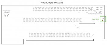
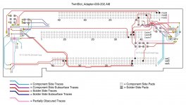
Whole PCB w/Key

TwinSlot_Adapter-000-202.jpg

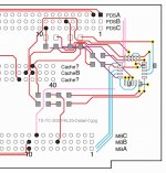
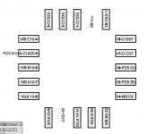
25pin PAL Detail

TS-TC-202-PAL25-Detail-0.jpg

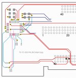
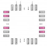
28pin PAL Detail

TS-TC-202-PAL28-Detail-0.jpg

If you PM me a realmail address I can attach a PDF, Illustrator 8 (OS9) file with layers a/o an EPS Export (dunno about the layering) or whatever I can do to help. I hope this board layout view isn't too confusing, it's the best way I've found to document the 3D model of a board as I see it developing in my head.

Looks like a lot of signals are held high, dunno what that adds in terms of trace buzzing complications? I hope it's clear how the traces pass through the resistors/whatever and continue on to make connections.

It might be a good idea to verify what I've documented first, then clear up what's partially obscured (pink) on the two PCBs and then move on to the balance of the board. As you verify the layout, I can knock the color coding back to grayscale for what's good to go in the overview and dump each color coded set of traces for each signal into its own layer for detailed examination.

Does that sound like a plan?

Happy hunting! :rambo:

edit: forgot to mention the pink pads on PAL28, those are the pins that look like they aren't connected to anything. Doesn't make sense, I'd think they'd be held high or pulled low if NC?

 
Last edited by a moderator:

Trash80toHP_Mini

NIGHT STALKER
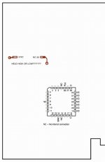
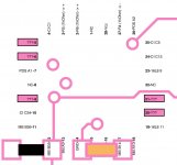
LOL! Here's another one for this go-round showing one more obscured trace I put into the latest file and the "Peripherally Involved?" traces/pads layer not included in the PDF?

TS-TC-rev200Delta-Periphery.jpg

How'd the attachments work out? I'm wasted for the time being! :blink:


off

Member
Well - that was fun :) You did pretty much most of the hard work; I have merely put my multimeter to good use and verified most of your connections.

Unfortunately, what you can do in Illustrator, I can't even dream of - so here is my version, about 99% finished (except for 5 pins on the 20L8 everything is mapped out and mostly verified).

Please forgive my colouring everything, if that doesn't make sense to you. It's pretty simple, really - every connector (MB, PDS, CI) has its color, every row (A,B,C) has its own shade.

Obviously this dictated name: 120 Shades of Pins

Hopefully I can finish the missing pins tomorrow, if not maybe you can figure them out. I fear, though, that this would require desoldering the chip as I cannot come up with a way to find the traces otherwise.

PowerCache 120 Shades of Pins.pdf


Attachments

  • PowerCache 120 Shades of Pins.pdf
    119.3 KB · Views: 127
Last edited by a moderator:

Trash80toHP_Mini

NIGHT STALKER
LOL! Now I get to do some hard work translating your tables into something visual so that I can understand it! My head doesn't grok tables or conventional schematics. :-/

There's a resounding silence in here  .  .  .  hopefully someone else will jump in to help flesh this stuff out so everyone can understand it?


Trash80toHP_Mini

NIGHT STALKER
I was doing some housekeeping and found a boo boo. While adding individual pin designations for each connector and correcting the number of positions on one of them, I noticed I had a connection I'd put in that was very different from what's obvious on you sticker-free board.

View attachment 11819

The correction is obviously shown in bold. ;D


Trash80toHP_Mini

NIGHT STALKER
Please let me know if I've put the labels for the connections in correctly on the Pads of the two PALs. Once I changed the nomenclature from "CIA 30" to "CI A30" it began to click. Still can't make heads or tails of you columnar data presentation, but I think I grok the pinout/signal tables.

20pin-PAL-Connections.jpg

28pin-PAL-Connections.jpg

It's interesting that the two PALs are interconnected(?) on your board. The NuBus Mafia scan over on 'fritter doesn't have the 16L8 pads populated, yet it would seem to work in the IIsi. Curiouser and curiouser!


Trash80toHP_Mini

NIGHT STALKER
Some of the lost traces may be connected to the thruholes underneath PAL28, test for connectons on the solder side.

 
Last edited by a moderator:

off

Member
Okay, good news and bad.

Starting with the good: I was able to trace out 4 more pins, you were correct, I needed to trace them from the solder side. Did so in my first try, but must have not pressed hard enough.

That leaves the bad: I cannot, for the whatever reason, find a connection to Pin 21 of the 20L8. It does not connect to any other pin on this chip, the 16L8, or any pin on any connector. And I checked them twice.
That only leaves one conclusion for me: This pin is, for whatever reason, left floating. Or my card is somehow broken but still works in the SE/30.

As for your images: As far as I can see all connections are correct (and I've adopted your naming scheme), the Pins 8 and 22 of the 20L8 are in fact connected to Ground (you've asked before, sorry for missing that).

PowerCache - 121 Shades of Pins.pdf


Attachments

  • PowerCache - 121 Shades of Pins.pdf
    119.8 KB · Views: 56
Last edited by a moderator:

Trash80toHP_Mini

NIGHT STALKER
Great job, thanks ever so much.  [:)] ]'>

I've got two more adapters in hand to model and I'm not expecting to have no new questions raised by either of them. What's very surprising to me is that there are what seem to be discrete connections between the two PALs. That PCB layout would appear to be (presumably from the 'fritterpics) fully functional in the IIsi without PAL20 on board. The SE/30 is a very strange duck with its video implementation at PseudoSlot $E, so I imagine you'd need both PALs on board like you have for compatibility there.

Did you make certain that neither of those traces are connected to the same pin somewhere in between the PALs? I've seen that kind of thing on Active Component SIMM-Savers I've modeled for the SIMM-Spender project. Or it might have been on another Active Component PowerCache Adapter? Dunno, it all gets jumbled together sometimes when I get tired or bunt out on a project. When I go back later to take another look I usually find something new while unraveling the mess.  ::)


Trash80toHP_Mini

NIGHT STALKER
Thanks for the feedback, there was a very hollow, echoing reverberation in here until very recently. :-/

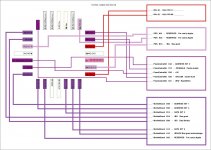
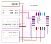
This is close as I can get to a translation of my file and off's tables to something vaguely resembling a schematic:

TwinSlot_Adapter-000-304.JPG

Suggestions on how to clarify the presentation would help. Lots of questions raised and I've got no answers, it's time for some input from you EE types hiding out there. :approve:

Error checking against off's tables would be much appreciated from anyone at all. You just can't proofread you own work.  ;)


rsolberg

Well-known member
Don't take the silence as a lack of interest. I've been following this thread with fascination, but haven't felt I had anything of value to contribute. Seeing off's post with a picture of the UnobtainiumAdapterModule was immensely satisfying. The anticipation of your response was rather exciting. Keep up the good work!


macosten

Well-known member
To come out of lurking - this is exactly the kind of thing I hope succeeds. Also hopefully, it'll cost less than Artmix's $249 TwinSpark adapter :p

...I might need to make a Trading Post post about it, but I'm not certain about it yet.

Good luck developing the board  :beige:


Trash80toHP_Mini

NIGHT STALKER
It's really good to hear from you guys! I certainly can't do this on my own, just dreamin' the impossible dream. I'm trying to lay the groundwork for our resident boffins to take up the challenge.

FWIW, I expect this to be an open source project with more than a few participants or it'll never get done. Pricing would depend upon participation and economies of scale. Not gonna get involved with that, this is for just for fun and one adapter for my SE/30 and maybe one for the IIsi..

Meanwhile, back at the pickle plantation:

TwinSlot_Adapter-000-305.jpg

I spent the day with my toys, mostly Illustrator, pics of the hacks and condensing several trays of goodies into a couple of project boxen of manageable proportions.

edit: a trading post post about what?

Anyways, I'm putting together a .PDF right now with both sides of the equation. How do I attach it for download? :?:

 
Last edited by a moderator:

macosten

Well-known member
edit: a trading post post about what?
About how I may or may not be looking for a TwinSpark Adapter or equivalent (this does the job of "Split SE/30 PDS slot into IIci-cache and PDS Passthough", I think, anyway). :p

I wish I understood schematics better than I do right now, but maybe if I stare at them hard enough, I'll understand them better. Unlikely to happen at 1:30 in the morning, though!

Somehow, it strikes me as... not the most complicated schematic I've seen, so perhaps it won't be the toughest thing to manufacture? I honestly have no clue, but it gives me hope.

Hopefully, my hope gives you the hope to continue, among everyone else's hope - because this is looking like a great project so far.


Trash80toHP_Mini

NIGHT STALKER
This chapter is about done, other than error checking and general research until someone else chimes in. I've gone about as far as I can with this adapter without help, so I guess a project summary for the overall cloning project is in order:

TwinSlot is a crucial line of research because its adaptation is splayed out across PDS, PDS passthru and the IIci Cache Slot adaptation. It also happens to be needed in two of my ProjectMacs! I wasn't expecting to see those connections to signals reserved for Apple's internal use, at least not the one to the Logic Board, that will likely prove to be problematic. The undocumented RESERVED connections on the adapter were not entirely unexpected. They could well have been hijacked by DayStar for internal use within the adapter itself with no connection at all to the PDS. That's a rolled up sleeves dirty trick I've considered playing on the motherboard of the IIsi itself using the traces of entire buses for my own nefarious purposes while the CPU thinks they're offline.

I've got adapters for the Mac IIx and the Mac II to model like this as the next steps of the overall Cloning Project. They'll be much easier to unravel as I'll be desoldering the connectors and active components so scans will be available of all traces on the outer layers. There will be little guesswork involved there! :D If needs be I can remove ALL components to buzz connections unimpeded by resistors holding signals high or low.

The IIx is interesting because it has only one small GAL on board, so it's far less complicated than the TwinSlot. It lends itself to coming up with an acceptable either/or solution for my two target systems and completes the process of cloning that adapter once we can derive or brute force the truth table secrets lurking within that one simple GAL.

The Mac II PowerCache adapter is fascinating in its complexity because it has a GAL, a PAL and a PROM on board. It plugs directly into the sockets for the discrete 68020 CPU and 68851 MMU on the motherboard. The CPU is removed and socketed on the adapter alongside the connector for DayStar's IIci Cache Slot implementation. The 68851 drops out of the picture at his point as its functions are taken on by the (surprisingly less capable) MMU implemented within the 68030 CPU. The Mac II adapter should actually be less complicated in terms of divining the functions of its three discrete active components because both 68020 and 68851 are fully documented, unlike the the ASICs infesting later iterations of the II series. The only fly in that ointment might be those pesky RESERVED pins on the IIci PDS. Fingers crossed gang!

I'm hopeful that when all three (fortunately that's four with off's confirmation that the IIsi TwinSlot works in his SE/30) Mac's adapter schematic PDFs are printed on legal paper and laid out in column for markup that patterns will become apparent.

Because the Mac IIcx has a passive adapter (no active components) these three PowerCache adapters will complete the puzzle for the entire Macintosh II series architecture other than its IIfx offshoot, it being beyond the ken of mere mortals. As far as I'm concerned it's an elegant black box to be treasured as is. Not to mention that it is one BIG@$$ platinum windmill better given a wide berth, I'm not poking sticks at that sucker!

edit: forgot to mention that I'd REALLY appreciate several of you proofreading my "schematic" of the TwinSlot. Proofreading one's own layout is impossible, contrary to my ex-partner in the sign business. He never could understand that, being impatient about doing it for me on my layouts.  ::)   Checking the tables in off's wonderful 120 Shades of Pins PDF against my schematic PDF is an absolute necessity.

off, if you could double check your tables and buzzing results it would be much appreciated. Finding out that that RESERVED connection to A2 on the motherboard is an error made by either of us might not be exactly a dream come true, but it sure would be nice to have it turn out to be a nightmare avoided!

Suggestions form those of you conversant in schematic development and in reading the blasted things IRL for turning this graphic representation into a actual schematic presentation would also be much appreciated. Confirmation that it's "good enough" as is would be even better news!

 
Last edited by a moderator:
Top