• Updated 2023-07-12: Hello, Guest! Welcome back, and be sure to check out this follow-up post about our outage a week or so ago.

How to tell if SE/30 has been recapped?

Crutch

Well-known member
Hi everyone, I’m new here and have found the forums to be incredibly helpful (thanks)!

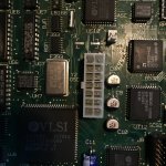
I recently got my hands on an SE/30 that was supposedly recapped but I have my doubts. The caps look exactly like the originals based on photos I’ve seen, and it looks to me like there’s a bit of residue around the bases. Is there a way to tell whether these are really old, or someone just replaced them with really authentic vintage looking new caps?

By the way I started having doubts because I think the SCSI chip is bad (haven’t tried cleaning it yet - that’s next). I’ve tried connecting several known good drives to the internal SCSI and it will only see them for a few seconds, if at all, before I get random crashes. There is definitely some black crud around the SCSI chip pins. 

Thanks for any thoughts!
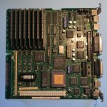
9227C029-99C9-450B-A0A1-C01EA712569D.jpeg

918C95BF-A6AA-4F01-80FC-E562E6BB09E9.jpeg

 
Last edited by a moderator:

Alex

Well-known member
I recently got my hands on an SE/30 that was supposedly recapped but I have my doubts. The caps look exactly like the originals based on photos I’ve seen, and it looks to me like there’s a bit of residue around the bases.
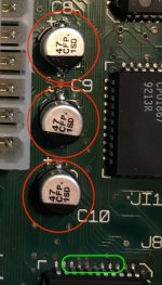
Personally, I think that those caps are not original from the sourced photos. They are not perfectly straight, they look like they were placed by hand. If you believe they are leaking replace them. Unless it is some flux that was not cleaned off.

Whatever you do, DO NOT use a set of pliers to grip and twist the caps, there is a very high probability that pads can get ripped off the board which involves nothing but more labor. Personally I add heat on each side and go back and forth with the iron from + lead to - lead until I can feel that enough heat has started to help loosen the cap at which point, with pliers in the other hand I grip the cap and very slowly and lightly begin to lift the cap and use my senses to determine if I can pull on side up. The key is to use flux to create a pool of heat. I set my iron to 400°C.

What else, well let me know if this helps. Oh, by the way, if you can, buy yourself a dead logic board or computer, any device really, that has caps on it, use it to practice on if you are not confident of your skills. I did this when I was starting off, which I feel that I am still in the midst of. I guess one never stops learning. Also, my method, at least with my skills does mean time gets taken up, it will take a while to get the cap of as things take time to get hot enough.

In RED

These definitely look like someone installed these by hand and it looks like flux residue. I guess you could check if it is flux which I am fairly convinced that it is but I would replace these with tantalum caps.

In GREEN

I would add some flux around any of the legs on chips and then hold the soldering iron at the end of the leg (attached to the board) to reflow that solder. The flux will help destroy the corrosive look. It should look shiny by the end. Flux helps clean and cause nice reflows of solder. Clean post reflow with isopropyl alcohol on a cotton swab, repeat if necessary and add a tiny amount of solder if you believe it is need. Alternatively, add flux to the green area and use a soldering braid to remove solder over that corrosive looking area then clean, then add more flux and return some solder back to that spot. You will know you have it right when you finally clean it and see a nice shiny finish to the solder. Don't put too much or too little.

If you ask me, PACE has some of the best videos on soldering, this 9 part series, if you ask me is a prerequisite and will go through good soldering practice.

I hope I of some use to you and the repair journey you are on. 


Screen-Shot-2018-08-18-at-4.20.52-PM.jpg

 
Last edited by a moderator:

tanaquil

Well-known member
If you ask me, PACE has some of the best videos on soldering, this 9 part series, if you ask me is a prerequisite and will go through good soldering practice.
I love those videos, and the vintage quality just adds to the experience. The 1970s called, they want their high school projector back.


Crutch

Well-known member
Thanks for the thoughts everyone.  Glad to know the board had been recapped.  I washed the board then cleaned with rubbing alcohol -- looks much better, most of the pins are nice and shiny now.  Tried it out and got chimes of death at first, but probably just hadn't let it dry enough -- used a hairdryer to dry it out thoroughly and it came on nicely to flashing question mark.  Still won't see a hard drive, but some progress with the SCSI issue -- I now see a continually (once/second) blinking LED on my internal SCSI2SD during the flashing question mark (before cleaning, I often didn't even get that).

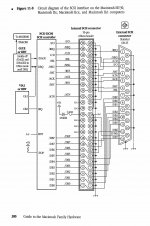
Sooooo I grabbed the SE/30 schematics and this very helpful diagram and started checking continuity on all the SCSI chip pins.  It looks like pin 20 (D31) on the 53C80 isn't connected to anything (it should be wired to pin 28 on both VIAs (UK11/12) and pin 19 on the VROM).  Every other pin has good continuity to where it's supposed to go.  The bad pin 20 visually looks good but oddly it's not even showing continuity to what I think is supposed it be the via connected to it on the other side of the board.  Is it possible some cap juice or something got into that via so it's not conducting?  If all else fails I'll try adding a jumper to UK11 but obviously would rather get this working as it should.


Alex

Well-known member
The bad pin 20 visually looks good but oddly it's not even showing continuity to what I think is supposed it be the via connected to it on the other side of the board.  Is it possible some cap juice or something got into that via so it's not conducting?  If all else fails I'll try adding a jumper to UK11 but obviously would rather get this working as it should.
Congratulations for getting this far and for taking note of continuity. Very carefully follow the trace and all relevant points of connection using a magnifying glass. If you can not find anything wrong, I think you will though, unless the trace travels beneath a chip in which case it will be invisible to you in that section.

So you are doing a visual examination of that trace and the connection points. Check to make sure that on either end of the trace there is nice and shiny connections, if not you may need to clean the two points at the end of the trace. So if necessary add some flux to those end points where the trace makes its end to end connection and using your iron heat those end points to burn off any corrosion. You want to make sure the connection points are as clean as can be. There is also no harm using a thin solder braid to pick up any dirt or corrosion that might still remain. After using the braid to clean that area, clean off the remaining flux thoroughly and then add a little flux and add a minuscule amount of solder, just drop because between the two ends of the trace are likely small connection points. So the idea is clean up those ends, especially if you see no damage to the trace.

Remember not to plug anything into SCSI while the Mac or the SCSI device is powered up. They are not hot pluggable, SCSI never was.

So as much as you reported a clean board, much cleaner than before, those two points at each end of the trace might have corrosion still there, so clean up some more and then reflow new solder and of course carefully examine the trace itself for any questionable area.

If doing the above doesn't yield any positive results then you may need to run a jumper cable. I recently took an old RJ45 cable (normal phone line) and stripped out one little wire, added some solder to the expose copper tips of the wire, bent the wire to fit snuggly so that it doesn't get caught to something when reinserting the board or when removing it. That's something to remember with the little strip of wire for the jumper, use a clean wire from some old cable, check for continuity on the cable you plan to use, add a dash of solder to both ends of the cable, bend the cable to shape and try to cut it to the required length (don't let it hang way out above the board or it can get caught on something, come loose and cause a short). To solder the first end of the cable, add a little bit of non-aggressive tape something tacky to hold down this little cable, solder the first end and then the second end. Remove the tape and clean off any residue the tape and flux used for soldering might have left behind. Check for continuity again and if it's good, test the SCSI issue.

----

If you used tap water for cleaning this is something you should have absolutely avoided because tap water contains ions that are a result of dissociating various salt compounds and those salts can get left behind as residue when the water evaporated. Over time, these salts will react with atmospheric humidity and cause corrosion in metal surfaces.

I tend to clean boards (rarely though) by pouring a little isopropyl alcohol while the board is angled on a platter where the isopropyl alcohol can get collected. I use light brushing action with a non-conductive brush to clean out the board. You can use distilled or deionized water for cleaning followed by isopropyl alcohol to run or push all that water off. Use an air can to spray off liquids from under chips and so on and then let it sit at least 24 hours. After that time you can use a can of air again to spray under components that might have held on to some humidity.

----

Of course, don't forget to work with ESD safety in mind. https://www.youtube.com/embed/tcRqj9FhgcE

 
Last edited by a moderator:

Crutch

Well-known member
Thanks @Alex for the great and thoughtful advice (and that diagram is terrific).  I will try it out this weekend and let you know how things go!


Crutch

Well-known member
Thanks again for the help.  After trying to clean with flux and desoldering braid, and spending a lot of time following the traces, I ended up where I started ... all the traces from the SCSI chip seem to be good, but that the first thing pin 20 on the SCSI chip seems to do is go straight through the board on a via ... and the point on the other side still wasn't showing any connectivity back up to the chip.  (There had been some crud in the area from the nearby caps -- I'm assuming they somehow corroded the via in a non-obvious way?)  Anyway -- after practicing for hours I finally got up the nerve to solder a jumper from that pin on the SCSI chip directly to where it needed to go on one of the VIAS ... and it works perfectly now!  Wish I could have fixed it without the jumper, but thrilled it works.

The schematic was helpful - thank you.


Alex

Well-known member
Anyway -- after practicing for hours I finally got up the nerve to solder a jumper from that pin on the SCSI chip directly to where it needed to go on one of the VIAS ... and it works perfectly now!  Wish I could have fixed it without the jumper, but thrilled it works.
Fantastic work, outstanding! I always love to hear these success stories. Don't worry about jumper cables, sometimes it ends up being the fix. As long as you have good solder joints and the ends of the wire are short enough to avoid a short and that the cable, if long, or short for that matter is secured so that it does not bump into something if the board has to be removed again it's a well done job. Kudos! Delighted that you fixed the machine. I have to say that even though these are old and slow machines they are a joy and a lot of the reward comes from fixing these sorts of problems — it really is rewarding to see it all come back to life.

Congrats!


Crutch

Well-known member
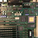
@tanaquil sorry for the delay, I didn’t open her up again for a week ... here’s a photo showing my amateurish jumper job.  I used #22 AWG wire from a 140-pack of various lengths I bought on amazon for $6 due to laziness (https://www.amazon.com/dp/B014JOV4TI/ref=cm_sw_r_cp_tai_25sLBbY264TCM) which worked perfectly and made it easy to practice a few times on a junk board first. Nicely bendable and holds its shape flat to the board. The electrical tape wasn’t really needed but the wire ends were maybe 3mm too long and I’m paranoid about it getting jostled and a wire end shorting to another pin (it’s really quite stable where it is though). I would make the wire ends shorter if I had to do it again. 

959F5045-2B1E-4474-8892-BEAD4C3A4214.jpeg

 
Last edited by a moderator:
Top