• Updated 2023-07-12: Hello, Guest! Welcome back, and be sure to check out this follow-up post about our outage a week or so ago.

Early Macintosh home brew 4MB memory upgrade board development

On and off over the past 5 months I’ve been working on a design for a memory upgrade board which will max out my Mac 512K at 4MB of RAM. I haven’t come across any projects like this in my searches, but if it’s already been done please let me know.

I’ve made a schematic with some notes regarding my thinking, and I’d like someone else with knowledge of Macintosh memory addressing to review it as a sanity check.

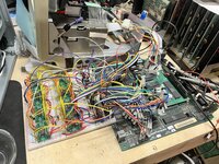
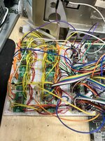
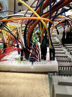
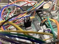
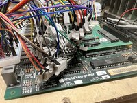
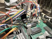
I did assemble the circuit on a couple of breadboards, but it was an absolute mess, and due to some combination of poor connections, lead impedance, and potentially interference, it didn’t work.

My next step is to go straight to laying out a PCB as a prototype to do a real test. I’ve got some fairly precise measurements to take to ensure pin headers will correctly find their way into sockets installed on the logic board. But before I spend too much time on that, I would really appreciate a sanity check on the design.

Some background:
The main part of design consists of the application of two existing techniques for upgrading memory:

One part creates a new RAM address signal, RA9F, which is created by taking VID/~u and C2M as control inputs to one half of a dual 4 input multiplexer. Address lines A19 and A20 are connected as two inputs to the multiplexer. The remaining two inputs are tied high. C2M selects between A19 or A20, and if VID/~u is high (video hardware accessing memory) then the output RA9F is held high to help keep video accesses at the top of memory. This technique is how RA8F is created when upgrading from 128K to 512K, and I believe it’s similar to how a stock Mac 512K creates this RAM address signal. Outlined in a mod described here: http://dserver.macgui.com/Dr Dobbs Fatten Your Mac 1985.pdf

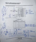
The other part creates additional CAS lines to select between additional RAM ICs. This is done by taking A21, ~CAS0, and ~CAS1 as inputs to a 3 to 8 demultiplexer to create ~CAS0F, ~CAS1F, ~CAS2F, and ~CAS3F. When A21 is low, ~CAS0F and ~CAS1F are controlled like they would be normally. When A21 is high, those two CAS lines are held high and ~CAS2F and ~CAS3F take their place. This is similar to a classic 1MB mod described here: https://archive.org/details/Classic_Mac_Tech_Info.PDF/page/n12/mode/1up

One concern I had was ensuring video hardware memory accesses are kept at the top of RAM. Its mentioned here that on stock 128/512K Macs there are hardware pull ups on the address lines, so that the address lines will float high during video memory cycles: https://web.archive.org/web/20230822174017/https://macgui.com/news/article.php?t=470
However, there are no hardware pull-ups for A21. I’ve checked the schematic and confirmed with a resistance check between A21 and the 5V rail.
I suppose I could just add a pull up resistor to the address line, but instead I cascaded the two main portions of the mod by utilizing the unused half of the dual 4 input multiplexer to select A21 as an input to the CAS generating demultiplexer when VID/~u is low, and forcing it high when VID/~u is high regardless of the actual state of A21. In that case the upper CAS lines (~CAS2F and ~CAS3F) are only accessible.

I could see a few ways to go about adding new memory ICs in different configurations. Either leaving the RAM address signals alone and add many more CAS lines for 256K ICs, or use 1MB ICs, or maybe SIMMs, but in the end using 4-bit DRAM ICs seemed to make sense for less ICs and hopefully less generated heat. The issue is that these ICs are not dual ported. Their output data are already buffered on the logic board, but their input data needs to be buffered, so the addition of tristate inverters suits the need.

Does anyone know if the Mac makes use of dual ported memory in a way that doing as I show in my schematic would prevent this from working?

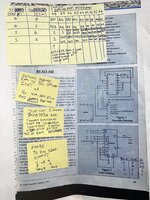
In addition to the schematic, I attached a couple of my old notes. Some may not be relevant, but I still find it useful as those mods of which this design is based on do not provide very good schematics to explain how it works, and my notes helped me work through it.
 

Attachments

  • MacFatty Memory Upgrade v2.pdf
    576.4 KB · Views: 7
  • IMG_4901.jpeg
    IMG_4901.jpeg
    2.4 MB · Views: 34
  • IMG_4900.jpeg
    IMG_4900.jpeg
    3.7 MB · Views: 42
For fun, here are some photos of my failed bread boarding attempt. I got some pretty flashing lines, and with enough wiggling of the wires, I could barely make out the image of a sad Mac through the lines!
 

Attachments

  • IMG_4659.jpeg
    IMG_4659.jpeg
    4.4 MB · Views: 38
  • IMG_4667.jpeg
    IMG_4667.jpeg
    2.5 MB · Views: 32
  • IMG_4666.jpeg
    IMG_4666.jpeg
    1.7 MB · Views: 25
  • IMG_4665.jpeg
    IMG_4665.jpeg
    2.6 MB · Views: 26
  • IMG_4660.jpeg
    IMG_4660.jpeg
    2.8 MB · Views: 21
  • IMG_4664.jpeg
    IMG_4664.jpeg
    3 MB · Views: 32
  • IMG_4668.mov
    12.1 MB

Juror22

Well-known member
So sorry that I will be no help at all, other than a supportive, "Man! That is really cool!" Even if you haven't got it quite working yet. I've been looking into working up some memory modules for a Zenith laptop (someday), but I'm still doing research on it.
 

olePigeon

Well-known member
Looks like you got pretty far, nice work. I'm also electronically useless. I feel like these old upgrade books are a gold mine for new, cheap upgrades and mods.
 
Thank you both for the encouragement. I’m pretty motivated to make this work. It would just be very disheartening to layout and PCB, pay to get a few made, then build one out just to find out the entire design was doomed from the start. If you know of anyone who may be interested in taking a look at my schematic and noodling with it for a bit, I would really appreciate it.

I suppose I could place some prototyping areas onto the PCB just in case it needs some extra logic or other bodges to get it working.

I’m in agreement that those old upgrade docs are invaluable! Studying them is what helped me understand how the Mac accesses its memory.
 

halkyardo

Well-known member
This is extremely cool! I'm not really familiar with the internals of the 512 to review your design in detail, but looking at your notes and the reasoning behind them, it seems like a sound idea to me. I'll be following this with great interest!
 

aladds

Well-known member
For what it's worth, breadboards are only really good up to 1Mhz. If you can slow the Mac right down it might actually work, assuming the circuitry is correct. If I get some time over the next few days I'll take a look at your design and let you know if anything pops out at me :)
 

Snial

Well-known member
Do you have an original 64K ROM or a 128K ROM? There's a Mac GUI post about boot up on a 64K ROM which describes the memory size test: basically it checks a 128K mirror address and if it's not a mirror it assumes it's 512K - it doesn't actually check all the RAM properly. I think it means you'd need to mod the ROM or add an INIT that checks RAM properly (or you specify the actual size in another System resource and you set up the system heap, stack and memory size accordingly).
 
Do you have an original 64K ROM or a 128K ROM? There's a Mac GUI post about boot up on a 64K ROM which describes the memory size test: basically it checks a 128K mirror address and if it's not a mirror it assumes it's 512K - it doesn't actually check all the RAM properly. I think it means you'd need to mod the ROM or add an INIT that checks RAM properly (or you specify the actual size in another System resource and you set up the system heap, stack and memory size accordingly).
I’ve got the 128K ROM. I know this because they’re installed in a third party SCSI card, and the system has a 400K drive. Good catch!
 
For what it's worth, breadboards are only really good up to 1Mhz. If you can slow the Mac right down it might actually work, assuming the circuitry is correct. If I get some time over the next few days I'll take a look at your design and let you know if anything pops out at me :)
On top of that, these breadboards are a little worn out from use in other projects, and they were very low quality to begin with.

And thanks! I’d appreciate the second set of eyes.
 

Builder68

Active member
It sounds like you've put a lot of thought and effort into designing this memory upgrade board!

While I'm no expert like you, here are some thoughts...

The Mac 512K likely doesn't use dual-ported memory. Standard DRAM with data buffering on the logic board should work as planned.

Choosing 4-bit DRAM ICs with tri-state inverters for data buffering seems like a reasonable approach to minimize the number of components and heat generation. Less chips generally means less power consumption and heat to dissipate.

Your approach of using a demultiplexer to create additional CAS lines for selecting extra RAM ICs aligns with classic 1MB mods. The cascaded design with the other multiplexer to control A21 based on VID/~u is a creative solution to limit video access conflicts. This ensures the upper CAS lines (~CAS2F and ~CAS3F) are only accessible when video is not using memory. Looking good! Keep it up!

My wild guess for why it doesn't work (yet!) is probably related to the breadboard quality, as you mentioned. It might also be noise-related. Have you compared the noise level on your circuit to the original Mac's noise level when functioning normally?

On the other hand, I wouldn't want to diminish all the effort you've already put in. But have you considered reverse engineering one of the many RAM expansion cards that were popular 30 years ago for these early Macs?

You could then test it on your breadboards. Starting from a fully functional project would give you a solid foundation for introducing enhancements, like using 4-bit DRAM ICs.

Of course, if you don't have a physical board, many members of this community would be happy to share high-resolution pictures with you!

This project has been a blast! It wouldn't be too difficult to imagine these becoming modern RAM expansion boards for the 512K someday!
 

Builder68

Active member
I actually considered reverse engineering the Dove MacSnap RAM expansion board a while back. Luckily, I have some high-resolution pictures of the board that I'm attaching. Although the MacSnap is based on 1x256kb DRAM ICs, these pictures might be helpful for you to compare and verify your approach. (By the way, I recommend Gimp as a great image editor if you're looking for one.)

Also, you should take a look at these articles on MAC GUI (if you haven't already seen them).


They briefly mention how RAM expansions work by including additional circuitry to relocate the screen buffer.
 

Attachments

  • MacSnap.zip
    17.4 MB · Views: 4

dankcomputing

Active member
Also consider taking a look at the MacRescue, which is a great candidate for cloning. Adds up to 6MB RAM (4+2mb ramdisk only) and the Mac Plus SCSI hardware. Just add Mac Plus ROMs.

You could extend the design by adding a disable switch + ROM switcher, allowing the 128 to operate as originally intended when desired.
 

Builder68

Active member
One way to simplify your prototype could be instead of using individual 1Mb DIPs, get a 3MB or 1MB w/ SIMM sockets RAM expansion board for the Macintosh Classic.

One option is the 2024 820-0405-01 GW4406A, which you can find on eBay for $30 or less. This will reduce cable clutter, interference, and ensure reliable connections. As a benefit, the register/decoding/buffering circuitry of your prototype can then be consolidated onto a single breadboard.
 
The Mac 512K likely doesn't use dual-ported memory. Standard DRAM with data buffering on the logic board should work as planned.
Maybe dual ported isn’t the phrase for it, but the DRAM datasheet indicates a data input and data output pin: https://datasheetspdf.com/pdf-down/H/M/5/HM50256_Hitachi.pdf

The Mac’s schematic shows the DRAM data inputs are connected directly to the data bus, and the outputs are connected to some tristate buffers which are connected to the data bus. It looks like the ASG and a couple other sound related ICs are also connected to the DRAM outputs before the tristate inverters. So the sound hardware could potentially read data from RAM even if the ~RAMRD signal isn’t asserted. That won’t be an issue with my design, but I’m not sure if there are other scenarios which could cause problems.
My wild guess for why it doesn't work (yet!) is probably related to the breadboard quality, as you mentioned. It might also be noise-related. Have you compared the noise level on your circuit to the original Mac's noise level when functioning normally?
I haven’t tried measuring noise specifically, but probing signals on the breadboard certainly exhibited additional noise not found on the logic board. Supply voltage was a little lower too due to voltage drop. At this point I needed to make room on my workbench, so the breadboards have been disconnected from the logic board. I could try reconnecting it all, but I’m leaning towards going straight into a prototype PCB layout next.

On the other hand, I wouldn't want to diminish all the effort you've already put in. But have you considered reverse engineering one of the many RAM expansion cards that were popular 30 years ago for these early Macs?

You could then test it on your breadboards. Starting from a fully functional project would give you a solid foundation for introducing enhancements, like using 4-bit DRAM ICs.

Of course, if you don't have a physical board, many members of this community would be happy to share high-resolution pictures with you!
When I first started looking for info online, my first thought was to try to reproduce an existing design, but I couldn’t find any reverse engineered schematics for contemporary memory expansion boards. I was surprised to not see listings for them either. I would imagine most of them in existence are probably inside of assembled Macs! It would certainly be interesting to check one out. My only concern is that they all seem to use some of their own decoding logic in PALs/GALs which would need their logic equations dumped somehow. It’s probably a better approach than mine as less signals would need to be tapped from the logic board.

That makes me think of something else which should probably be addressed. My present design requires desoldering many custom Apple ICs for which there are no replacements. It was a bear to desolder them even with a decent Hakko desoldering gun, lots of flux, and solder wick. I would hate for anyone to ruin their logic boards or custom Apple ICs for this mod.

I recently watched an Adrian’s Digital Basement video which showcased a couple of early Macs with aftermarket memory expansion boards. These boards plugged into some logic board IC and resistor pack sockets, while other signals were tapped via bodge wires soldered to logic board vias/pads harnessed into a connector which plugged into the expansion board. That might be a good idea moving forward.

This project has been a blast! It wouldn't be too difficult to imagine these becoming modern RAM expansion boards for the 512K someday!
Thanks! That’s the plan :)
 
I actually considered reverse engineering the Dove MacSnap RAM expansion board a while back. Luckily, I have some high-resolution pictures of the board that I'm attaching. Although the MacSnap is based on 1x256kb DRAM ICs, these pictures might be helpful for you to compare and verify your approach. (By the way, I recommend Gimp as a great image editor if you're looking for one.)

Also, you should take a look at these articles on MAC GUI (if you haven't already seen them).


They briefly mention how RAM expansions work by including additional circuitry to relocate the screen buffer.
Thank you! I’ll try to dig into all of this soon.
 
Also consider taking a look at the MacRescue, which is a great candidate for cloning. Adds up to 6MB RAM (4+2mb ramdisk only) and the Mac Plus SCSI hardware. Just add Mac Plus ROMs.

You could extend the design by adding a disable switch + ROM switcher, allowing the 128 to operate as originally intended when desired.
Wow! They desoldered the entire CPU! I’ll check this out too.

I originally searched high and low for some of those IC sockets which snap on to the top of an IC and came up with very little results. That would be way nicer than desoldering and socketing a bunch of rare ICs. I think someone would need to 3D model and print some modern ones! I’m not sure how the actual contacts/pins would be addressed. But it sure would be spiffy!
 
One way to simplify your prototype could be instead of using individual 1Mb DIPs, get a 3MB or 1MB w/ SIMM sockets RAM expansion board for the Macintosh Classic.

One option is the 2024 820-0405-01 GW4406A, which you can find on eBay for $30 or less. This will reduce cable clutter, interference, and ensure reliable connections. As a benefit, the register/decoding/buffering circuitry of your prototype can then be consolidated onto a single breadboard.
I considered using SIMM sockets and SIMMS as DRAM but ultimately ended up settling on the ICs I have as I could get some decently cheap on eBay. I think a future final design should use SIMMs so folks can replace them easily if needed.
 
Top