• Updated 2023-07-12: Hello, Guest! Welcome back, and be sure to check out this follow-up post about our outage a week or so ago.

Color Macintosh Plus

sam256

Member
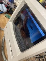
When I was a kid, I always wished my Mac Plus had color. Thirty years later...

Really just another Pi in Mac case project. A few things I did differently:

All the external ports are unchanged. You can plug in and use an original keyboard and mouse. (Tinkerboys USB adapters are soldered on the inside of the case)

“Working” floppy drive that accepts special 3D printed floppies with an SD card in it. (See video. A USB Sd card reader, 12 v motor pi HAT for the eject, a lot of patient measurements and 3D printing...)
 

Sound from the original speaker (Pi DAC/Amp hat)
 

Reused the original CRT glass front. (Cut open at your own risk!)
 

Use original power port and switch. (Wired out from the analog board)
 

Basically I tried to make this look externally as much like the original as I could. (Apologies in advance to those bothered by destruction of internal components on these.  But I have restored two other original Pluses so I’m net +1)


View attachment IMG_0500.MOV
1BA41ADC-F5D7-486F-8A6D-0E5EAEAE7B8F.jpeg


View attachment IMG_0504.MOV
1B95E86C-F93F-4599-A1B9-30184F15F14B.jpeg

26B03DE3-0EFE-45EC-9344-4C7CB616CDC9.jpeg

762CABB2-BE19-4D4A-B9C0-7395D774911A.jpeg


erichelgeson

Well-known member
Nice! I have a broken SE/30 tube/case I'm considering doing a project like this too. Can you talk more about how you cut the tube and what exact screen you used?

Oddly the videos are not playing for me, can hear them just not see them.


sam256

Member
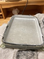
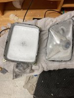
In terms of cutting the glass, there's obviously always some danger in messing with CRTs, so do at your own risk and only if you are comfortable.  That said, the basic steps were:

1. Wrapped it in a heavy towel and broke off the vacuum nipple at the very back end/narrowest part of the CRT to eliminate the vacuum.

2. Use a diamond cutting wheel on a dremel at under 10k rpms to cut around the edge near the screen.  It was important to go excruciatingly slow to avoid the screen cracking.  It will crack if it heats up _at all_ so I really needed to avoid the temptation to go fast.

3. Once I separated the front, i went over the jagged edges manually with the front of the diamond cutting wheel to blunt them.

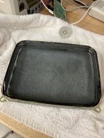
4. Water and a towel was able to wipe off the sliver coating inside.

5. I then polished the front and the back of the screen with a felt polishing wheel and cerium oxide.  I'm not sure that did that much.  

At the end of the day there were two things about the screen that concerned me: (a) it's darkly tinted; and (b) it has some stippling in the glass is distorting.   The tint didn't end up mattering because the LCD is bright enough.  The stippling does make the display appear noticeably fuzzier than the LCD alone.  That's probably the biggest negative to this.  If you try to run the screen at 1024x768 that will be very noticeable and annoying.  If you do at 640x480 as in the video its still noticeable, but fine in my opinion.

Here are some pics of the glass cutting.

For the LCD screen, I used an 8 inch, 4:3 ratio, 1024x768 Pimoroni.  Available here https://www.amazon.com/gp/product/B07HJ569V9/ref=ppx_yo_dt_b_asin_title_o08_s00?ie=UTF8&psc=1

62571116551__6DE3EF24-A39D-40F3-B453-45A573A18BD3.jpg

62570708762__3690F540-1866-4FB9-9C81-D924DABD9089.jpg

62570707543__60F7B997-FE6F-46EB-8FFA-99C9D96BF971.jpg


techknight

Well-known member
to make it more realistic, you could use a spray-on rear projection screen material, and then use a small LED pico projector. 


sam256

Member
The floppy drive: 

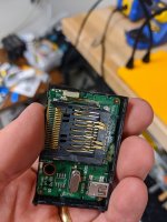
1. I found an SD to USB drive that I could pop the top off of to allow the floppy drive's mechanism to seat "down" on it.  I don't know the model I used--I just had one lying around.  I've attached a picture.

2. It had a little "presence" detector that was normally actuated by the SD card pushing to contacts together.  I rewired that to be triggered by the floppy drive's presence detector (which is also just a contact sensor that's pressed when a floppy goes in--it's on the bottom left of the drives "mouth").

3. For the eject, I used this https://www.adafruit.com/product/2348.  Basically a hat that you connect to your PI, wire in 12Vs of power, wire it to the floppy motor and then use a python script to turn it on and off.  I basically just followed the instructions for wiring and programming a DC motor.  The floppy motor is a simple 12v DC motor, which means you have to run the motor just long enough to complete the eject cycle.  I did it based on sound and the magic number seemed to be to allow it to run for 1.1 seconds to complete an eject cycle.

I did this part early on and didn't take many pictures unfortunately.  Here's a short video that gives a little better sense of how it works.  


IMG_20200402_114148.jpg


sam256

Member
Keyboard and mouse:

I used Tinkerboy's USB adapters

Keyboard: https://www.tinkerboy.xyz/product/tinkerboy-m0110-keyboard-to-usb-converter-for-the-apple-macintosh-128k-512k-plus-keyboard/

Mouse: https://www.tinkerboy.xyz/product/tinkerboy-m0100-mouse-to-usb-converter/

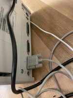
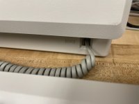
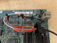
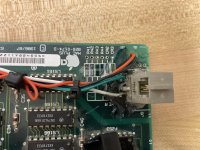
To keep the external appearance of the MacPlus I basically cannibalized the null-modem (for mouse) and Rj11 (for keyboard) connectors on the logic board and connected them to the usb adapters inside the case.

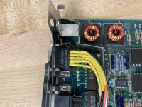
For the keyboard, this involved wiring the four leads from the RJ11 directly to tinkerboy's adapter.  In theory I should have been able to pick up the leads on the motherboard, but for some reason the power pins had a short if I went through the motherboard, so I ended up desoldering the whole connecter, bending those pins back and soldering wires directly to them.  I then put some epoxy around it to make sure it was mechanically strong.  Here are some pics.

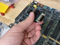
The mouse was a little more straightforward.  I desoldered the null modem cable from the logic board, bent back the pins, soldered wires from the pins to a male null modem cable, resoldered the connector to the logic board, and then just plugged it into tinkerboy's usb adapter.  Pics of that as well.

IMG_0385.jpg

IMG_0386.jpg

IMG_0387.jpg

IMG_0389.jpg

 
Last edited by a moderator:

sam256

Member
A few final things since I'm going into details:

Audio: the 3.5mm out from the Pi wasn't powerful enough so I used this hat for an amp - https://www.amazon.com/gp/product/B07CZZ95B9/ref=ppx_yo_dt_b_asin_title_o03_s00?ie=UTF8&psc=1

Wifi: I was worried that the case would block the wifi signal so I added a usb wifi dongle with external antennae.  As it turns out, however, the pi 4's built in wifi seems to work just fine even with the case closed up.  But I left the external antennae in anyway, taped to the back of the lcd. 

Keyboard and mouse: The single button mouse and limited mac plus keyboard are sort of annoying to use with modern apps, so i stuck a logitech wireless dongle in to allow me to use a wireless keyboard and mouse I have.

Screen: I printed a bezel for the LCD to cover up the silver and make sure it was center.  It is actually a bit of a tight fit in the CRT glass which is why the bezel is missing one side.  Here's the stl for it in case its useful.

I think that's it...

View attachment Mac Plus Screen Frame v6.stl


sam256

Member
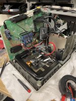
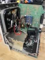
Another update -- I wanted to re-create the startup sound of the Mac Plus.  It bothered me to flick the power switch and _not_ hear the familiar "boing".  So I wired in this Ada Fruit sound board with a recording of the Mac startup chime and some floppy disk noises.  https://www.adafruit.com/product/2210. The card activates and plays as soon as the power is flicked on and then once the pi boots it disables it.

Here's a video and a pic.

If you look in the picture you'll see two speakers wired in.  The bootup sound file plays the "boing" over the left channel and the floppy drive sounds over the right channel and then i've placed the speakers so they sound like they are coming from the correct physical spots.

So now the bootup is a lot closer to a real Mac Plus bootup.  I get all the sounds I spent years listening to ("boing, chug chug chug") but then I get to play prince of persia in color.

I'd like to get the happy mac splash screen to show earlier, but this is a little tricky with the Pi 4's video driver.  Any ideas there are welcome.


IMG_0556.jpg


jonpurdy

Well-known member
19 minutes ago, sam256 said:

Another update -- I wanted to re-create the startup sound of the Mac Plus.  It bothered me to flick the power switch and _not_ hear the familiar "boing".  So I wired in this Ada Fruit sound board with a recording of the Mac startup chime and some floppy disk noises.  https://www.adafruit.com/product/2210. The card activates and plays as soon as the power is flicked on and then once the pi boots it disables it.

Here's a video and a pic.

If you look in the picture you'll see two speakers wired in.  The bootup sound file plays the "boing" over the left channel and the floppy drive sounds over the right channel and then i've placed the speakers so they sound like they are coming from the correct physical spots.

So now the bootup is a lot closer to a real Mac Plus bootup.  I get all the sounds I spent years listening to ("boing, chug chug chug") but then I get to play prince of persia in color.

I'd like to get the happy mac splash screen to show earlier, but this is a little tricky with the Pi 4's video driver.  Any ideas there are welcome.

Just found this thread. This is so cool! Love that you’ve added the correct sounds, especially playing from the correct part of the case. 


jimbojones

Well-known member
This really is fantastic. I've done my own Mac Classic to iPad screen/Intel NUC conversion which I'll write up at some point but without all of your awesome attention to detail with the CRT glass, floppy SD (!) and original ports for the keyboard/mouse.

Well done!

The only issue I've found with mine (I used an iPad 3 screen/HDMI board with pixels doubled to give 1024x768) is that that resolution seems a bit high for the small size of the screen, especially as old Mac software isn't usually designed to run that high (and I can't run it at a lower res as I get a big border).

 
Last edited by a moderator:

sam256

Member
The only issue I've found with mine (I used an iPad 3 screen/HDMI board with pixels doubled to give 1024x768) is that that resolution seems a bit high for the small size of the screen, especially as old Mac software isn't usually designed to run that high (and I can't run it at a lower res as I get a big border).


I've found 640x480 is really the sweet spot at this size.  I run basiliskII and vMac at that res at they are both able to fill to fit the screen (1024x768).  basiliskII handled it automatically.  vMac I had to play with the compile time options (or do it manually via the "ctrl" menu).


LaPorta

Well-known member
This is really awesome. I could totally do something like this for my always wanted but never built project: the MacArcade. Something I daydreamed up in high school some 20+ years ago: a Mac Plus or equivalent inside an arcade machine, with the keyboard and a trackball for controls, and floppy ports next to them. Stereo speakers out of the top and everything otherwise just like a real arcade machine. BDC on that thing, anyone?

 
Top