• Updated 2023-07-12: Hello, Guest! Welcome back, and be sure to check out this follow-up post about our outage a week or so ago.

Color Classic video problem

gbcs001

Active member
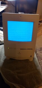
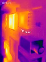
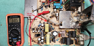
Hello, I'm new here and new to vintage Mac restoration. I bought a Color Classic on Craigslist for $200 that I'd like to get working again. It wouldn't boot, and the display shows retrace lines on an otherwise bright blue screen (see photo). After a good cleaning I found that both the logic and analog boards were in very good shape (no visible corrosion and no bad solder connections). After recapping the logic board, it still wouldn't boot and there was no discernible improvement in the display. I have not yet recapped the analog board. The AB is putting out +5 and +12 volts to the logic board, and the attached infrared image shows that logic board ICs are receiving power.

I'd like to resolve the retrace problem first and could use some advice on how to get started. Turning down the brightness pot doesn't help. Retrace blanking is obviously not working, but from where is that controlled? I don't see an IC on the PCB that's plugged onto the CRT neck, so am I right to assume it's controlled by the video processing (jungle) IC on the the analog board? Any pointers you guys could offer to find the source of the problem would be much appreciated.
 

Attachments

  • Retrace lines.jpg
    Retrace lines.jpg
    964 KB · Views: 42
  • FLIR image of logic board.jpg
    FLIR image of logic board.jpg
    972.9 KB · Views: 23

gbcs001

Active member
Yes, I found the pot, but adjusting it doesn't eliminate the retrace lines unless the screen brightness is reduced to black. It looks like the blanking pulses are missing from the video signal. Would that behavior stem from the video IC on the analog board?
 

gbcs001

Active member
I think the problem with my Color Classic is the logic board, not the analog board. The gray screen with horizontal retrace lines is normal when no video is sent from the logic board. Blanking of the retrace lines is contained in the video data as far as I have been able to determine. In any case I recapped the analog board with no improvement.

The CC will not boot, even after recapping the logic board. There's no chime and no organized display. The logic board has +5 and +12V power, and, as this thermal image shows, the M68030 and various other chips appear to be running. The main ram and video ram chips and scsi chips are cold, but that is to be expected under the circumstances.

FLIR image of logic board 2.jpgCC Logic Bd.jpg

I found a +5V 16 Mhz square wave clock signal present on pin 6 of the M60030. The logic board is, for the most part, alive.

Since first step in the boot process is to execute instructions on the two ROM chips, and that appears not to be happening, I need to determine if the masked ROMs have somehow been damaged. Both ROMs have +5V power at their Vcc pins, and as you can see in the thermal image above, there is some heat radiating from both chips.

What is the best way to test the ROMs? If I can read the data from the ROMs using a EPROM programmer, does that mean that the chip hardware is good? I will then have to compare the data with known good ROM data files. Does anyone have the binary data files for the CC ROMs? If the ROMs turn out to be good, are there other things I should check that could be preventing the machine from booting?

Thanks for any tips you can suggest.
 

gbcs001

Active member
As I suspected, one of my masked ROMs is bad. I purchased a XGecu T48 programmer (Amazon) and a 27C400 adapter (eBay) in order to read the contents of the ROM chips. The HI ROM couldn't pass the pin check. The LO ROM was readable. Interestingly, the adapter PCB was not completely compatible with the T48 programmer (TL866II-G3). The adapter has to be inserted with the ZIF levers opposite each other. The problem is that the adapter PCB blocks the lever on the T48 from fully opening the ZIF. I had to cut a notch in the adapter board to provide clearance as shown here:

T48 with Notch Mod.jpg

I compared the data on the Color Classic's LO ROM with that from a Color Classic II. I was led to believe that the CC II ROMs will work in the CC, which may be true, but I found a few bytes that didn't match. I decided the best course of action was to create the LO ROM binary data from the CC .ROM file that I downloaded from Macintosh Repository. I'm in the process of figuring out how to split the .ROM file into binaries for the HI and LO CC ROMs. I'll have to dust off my programming skills for that.
 

gbcs001

Active member
I wrote an Xcode Swift program that takes the ROM file, ECD99DC0 - Color Classic.ROM from Macintosh Repository, and splits it into the two binary files needed to program the EEPROMs needed to replace the masked ROMs on my CC motherboard. Actually, I only have to replace the Hi ROM chip, the Lo masked ROM data is good. The two 27C400 EEPROMs I ordered are due to arrive in a week or so. The ROMSplit utility that I wrote should work for other vintage 68K Macs, as well. The source code is on my GitHub repository.
 

gbcs001

Active member
BTW, I've attached the two binary ROM files for the Color Classic.
 

Attachments

  • HI_ROM.BIN
    512 KB · Views: 9
  • LO_ROM.BIN
    512 KB · Views: 9

gbcs001

Active member
I received my 27C400 EPROMs yesterday and programmed one with my XGecu T48 programmer to create a new HI ROM chip. Inserting the reprogrammed ROM chip did the trick. The CC chimed and showed the floppy icon with question mark. The display was way out of adjustment though. There were still horizontal retrace lines, but turning down the brightness pot on the analog board got rid of them. I installed a hard drive with System 7.1 and attempted to boot the computer. No luck. Turns out the CC requires System 7.5+. Using another Mac I was able to install 7.5.3 on the hard drive which enabled the CC to boot. I made more adjustments to the display, but as you can see in this photo the raster is not quite square. The bottom is narrower than the top. I wasn't able to correct this problem. Can anyone tell me how to do it? Is the raster shape controlled by the yoke rings?
 

Attachments

  • Color Classic.jpg
    Color Classic.jpg
    1.2 MB · Views: 25

imactheknife

Well-known member
I received my 27C400 EPROMs yesterday and programmed one with my XGecu T48 programmer to create a new HI ROM chip. Inserting the reprogrammed ROM chip did the trick. The CC chimed and showed the floppy icon with question mark. The display was way out of adjustment though. There were still horizontal retrace lines, but turning down the brightness pot on the analog board got rid of them. I installed a hard drive with System 7.1 and attempted to boot the computer. No luck. Turns out the CC requires System 7.5+. Using another Mac I was able to install 7.5.3 on the hard drive which enabled the CC to boot. I made more adjustments to the display, but as you can see in this photo the raster is not quite square. The bottom is narrower than the top. I wasn't able to correct this problem. Can anyone tell me how to do it? Is the raster shape controlled by the yoke rings?
Good job! How much to program a classic ii rom? One of mine is toast
 

gbcs001

Active member
I received my 27C400 EPROMs yesterday and programmed one with my XGecu T48 programmer to create a new HI ROM chip. Inserting the reprogrammed ROM chip did the trick. The CC chimed and showed the floppy icon with question mark. The display was way out of adjustment though. There were still horizontal retrace lines, but turning down the brightness pot on the analog board got rid of them. I installed a hard drive with System 7.1 and attempted to boot the computer. No luck. Turns out the CC requires System 7.5+. Using another Mac I was able to install 7.5.3 on the hard drive which enabled the CC to boot. I made more adjustments to the display, but as you can see in this photo the raster is not quite square. The bottom is narrower than the top. I wasn't able to correct this problem. Can anyone tell me how to do it? Is the raster shape controlled by the yoke rings?
It's not perfect, but I was able to improve the geometry of the CC's raster. It's all accomplished using the 7 right most potentiometers on the back of the analog board (once the yoke is adjusted to level the picture). The rings on the yoke are used for vertical convergence adjustment while the pot on the back of the CRT socket PCB is for horizontal convergence adjustment. I'm getting a tiny electrical spark when I power on the computer after its being off for awhile. It causes a band of static on the CRT. All caps on the analog board were replaced. Any idea what might be causing that?
 

Attachments

  • Color Classic 2.jpg
    Color Classic 2.jpg
    1.3 MB · Views: 20

gbcs001

Active member
Try as I might, I haven't been able to produce a nice clean rectangular raster shape. The upper right corner appears shrunken. Any hints would be appreciated.

CC Display Distortion.jpg
 

ymk

Well-known member
Try reducing the horizontal width.

Otherwise, you may need to increase B+ voltage to maintain a rectangular picture of that size.
 

gbcs001

Active member
I reduced the horizontal width with only a slight improvement of the raster shape. Does anyone happen to know the correct B+ voltage for the Color Classic and which pot controls it?
 

gbcs001

Active member
I found a YouTube video that Techknight produced while trouble shooting a CC analog board. He showed how to adjust the B+ voltage level to control the CRT's high voltage. He said that B+ should be about 71 volts to produce ~22,000V at the CRT anode. B+ on my board was only 68.5V which could explain the distorted raster. Unfortunately, the trimpot was glued tight and couldn't be adjusted, so I'll have to replace it with a new 500 ohm pot. To prevent the flyback transformer from producing high voltage, the B+ input to the flyback was removed at jumper J48.
 

Attachments

  • B+ Trimpot.jpg
    B+ Trimpot.jpg
    129.3 KB · Views: 28
Top